
Electric telescopic stick

a technology of electric telescopic sticks and telescopic handles, which is applied in the direction of walking sticks, mechanical energy handling, physical therapy, etc., can solve the problems of not using multiple thread screws and the inability of the stick to respond to the user's operation instantaneously

Inactive Publication Date: 2011-03-17
IWATA TEKKOSHOKK
View PDF3 Cites 6 Cited by
  • Summary
  • Abstract
  • Description
  • Claims
  • Application Information

AI Technical Summary

Benefits of technology

[0009]A battery for driving the electric motor is accommodated in the grip portion. Further, a buttery accommodation portion together with an electric circuit substrate may be provided on an outer side of the fixed stick portion. This increases the degree of design freedom of a configuration in the grip portion.
[0012]A space is provided between the fixed stick portion and the movable stick portion in order to make the movable stick portion slidable. Each slidable side of the fixed stick portion and the movable stick portion is subjected to friction reduction coating such as Teflon (registered trademark) coating so that the space between the fixed stick portion and the movable stick portion can be small to minimum. Therefore, rocks, sands, dusts, or the like can be prevented from being caught by the space.
[0015]Normally, when a screw is turned one revolution, the movable stick portion elongates or contracts by one thread. When the multiple thread screw is turned one revolution, the movable stick portion elongates or contracts for multiple threads. Therefore, the movable stick portion elongates or contracts faster. However, as the number of threads in the multiple thread screw is larger, the screw is turned by pushing a nut into the fixed stick portion when a load is applied at the time of use. This causes the stick to be contracted so that the stick is unable to support a user against the user's weight. In the aspect of the invention, the screw is prevented from reversely rotating by setting a ratio P / L of a length P of the pitch moving when the screw is turned one revolution with respect to a circumference L of the screw to 0.04 or more and lower than 0.1.

Problems solved by technology

However, these sticks cannot instantaneously respond to a user's operation because these sticks elongate and contract every time the user stands up from a chair or the like, the user goes up and down stairs, or the like.
However, a multiple thread screw is not used in any of these disclosed techniques for converting a rotation motion to a linear motion.

Method used


Image

  • Electric telescopic stick
  • Electric telescopic stick
  • Electric telescopic stick

Examples


first embodiment

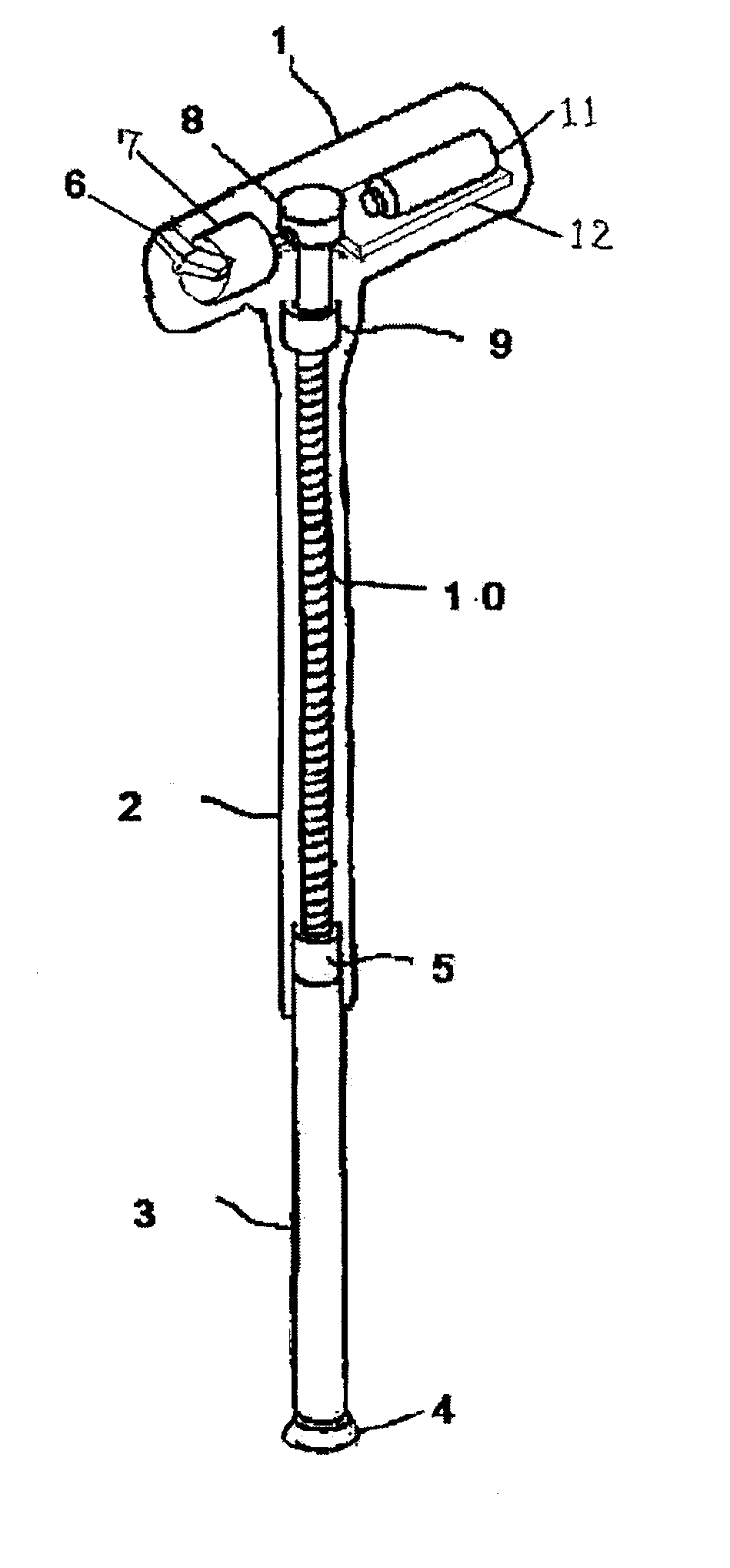
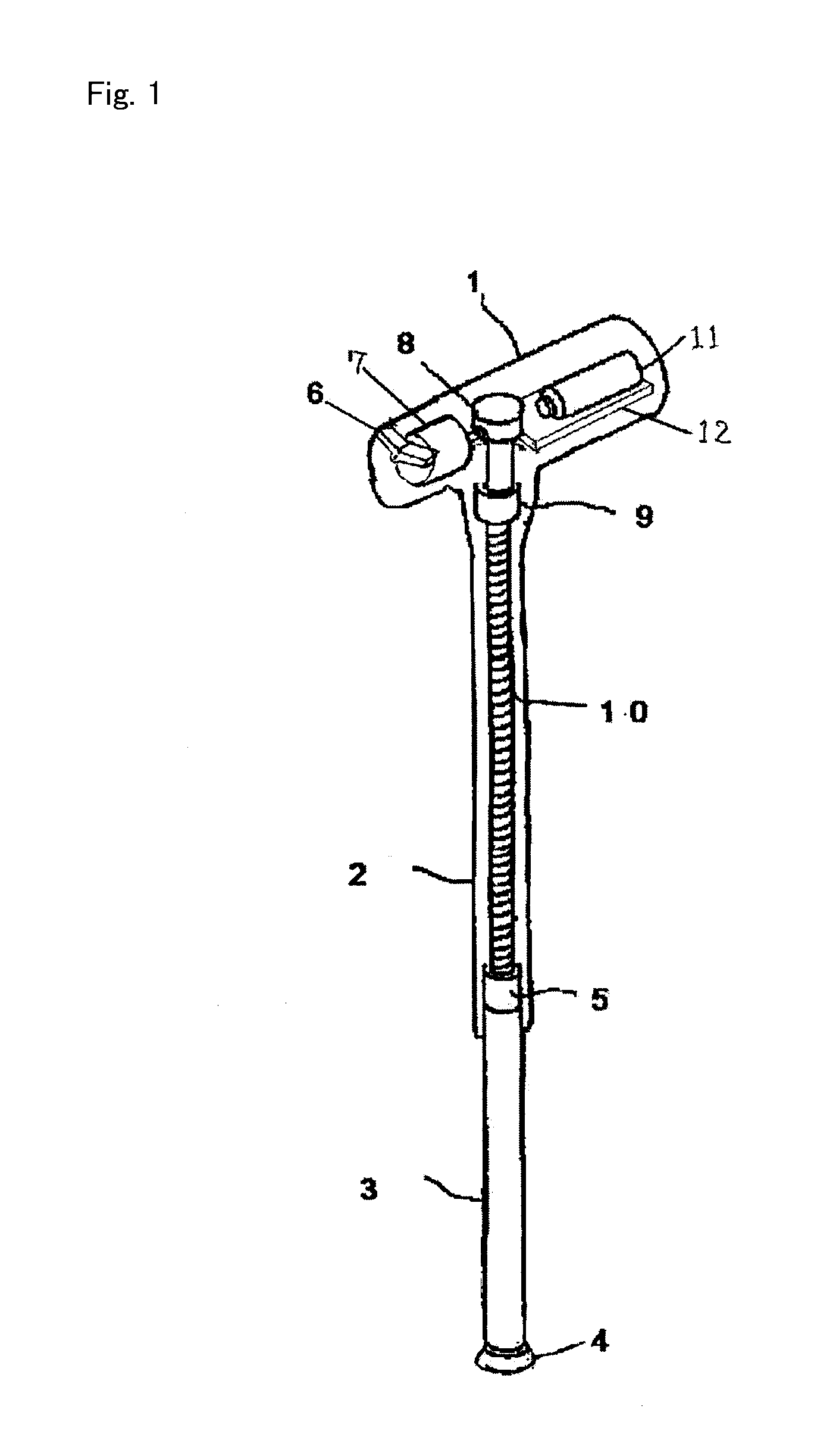
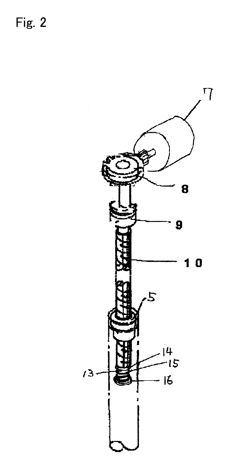
[0023]In FIG. 1 and FIG. 2, a fixed stick portion 2 and a movable stick portion 3 are formed with a hollow outer pipe and a hollow inner pipe, respectively. The fixed stick portion 2 and the movable stick portion 3 constitute a stick main body and are made of a lightweight metal material such as carbon pipe and duralumin having high flexural strength. Further, a grip portion 1 is attached to an upper portion of the fixed stick portion 2.

[0024]An electric motor 7, a control circuit substrate 12 for driving the motor, a lithium-ion rechargeable battery 11 and a switch 6 are built in the grip portion 1. The electric motor 7 is rotation-driven in the forward and reverse directions by operating the switch 6 in the grip portion 1. It is to be noted that an outer surface of the grip portion 1 is coated with flexible synthetic rubber or foamable resin flexible member.

[0025]The stick main body is composed of the fixed stick portion 2 having a large diameter and the movable stick portion 3 wh...

second embodiment

[0028]A buffer device composed of a slide metal member 13, a spring holder 14, a spring 15 and a sleeve 16 is built in a lower end of the multiple thread screw 10 as shown in FIG. 2. With the buffer device, the nut member 5 hits against the spring holder 14 when the stick is elongated to the maximum and the spring holder 14 is compressed by the spring 15. However, the clutch operates before the spring completely contracts so that biting of threads can be eliminated. From this state, the stick can be contracted without any difficulty by reversely rotating the multiple thread screw 10 by the switch 6.

[0029]In FIG. 3, an example of the clutch used in the invention is illustrated. The clutch operates only when the stick is elongated. Further, the clutch includes springs 26 and steel balls 25 which are accommodated in deep holes 24 and two abutment holes 23 which are provided on a surface of a multiple thread screw connecting axis 21 at a position opposite to the deep holes 24. At this t...


PUM


Abstract

There is provided an electric telescopic stick of which length can be easily adjusted quickly if needed by using only one hand by providing a multiple thread screw and providing a switch on an anterior portion of a grip portion including an electric motor which rotates the multiple thread screw in the forward and reverse directions. Further, in the electric telescopic stick, since a clutch is formed between the electric motor and the multiple thread screw, overload is not applied to the motor because the clutch idles when the movable stick portion is completely elongated. Further, a user can recognize the idling state from hitting sounds generated when steel balls are hit against holes when the clutch idles.

Description

[0001]The present application is based on Japanese Priority Application No. 2009-214208 filed on Sep. 16, 2009 with the Japan Patent Office, the entire contents of which are hereby incorporated by reference.BACKGROUND OF THE INVENTION[0002]1. Field of the Invention[0003]The present invention relates to an electric telescopic stick having a telescopic function for assisting a user in going up and down stairs, and in standing up from a chair or the like and sitting down, or the like.[0004]2. Description of the Related Art[0005]An existing stick has simply a bar shape. Further, there are a telescopic stick which is fixed by fitting a bush button into a hole and a telescopic stick which is fixed by tightly screwing. However, these sticks cannot instantaneously respond to a user's operation because these sticks elongate and contract every time the user stands up from a chair or the like, the user goes up and down stairs, or the like.[0006]On the other hand, sticks having an electric tele...

Claims


Application Information

Patent Timeline
Patent Type & Authority Applications(United States)
IPC IPC(8): A45B9/00H02K7/14
CPCA45B2009/007A45B9/00
Inventor IWATA, KATSUMI
Owner IWATA TEKKOSHOKK
Learn More