Floating Structure

a floating structure and structure technology, applied in waterborne vessels, special-purpose vessels, vehicles, etc., can solve the problems of long working period for double-hull change, high construction cost, and oil pollution of rivers and oceans, and achieve the effect of reducing construction costs and ensuring safety

Inactive Publication Date: 2011-03-17
TAISEI ENG CONSULTANTS
View PDF2 Cites 2 Cited by
  • Summary
  • Abstract
  • Description
  • Claims
  • Application Information

AI Technical Summary

Benefits of technology

[0022]Because the oil tanker or the oil barge of the single hull is put on the central tank and the wing tank, the oil tanker or the oil barge of the single hull is fixed with fixing materials, the oil tank

Problems solved by technology

However, the loaded cargo oil flows out from the damage part of cargo tank when damage to which single hull tears in some causes of the collision, grounding, corrosion, and breakage, etc. is received, and oil will pollute the river and the ocean.
However, double hull change takes long working period and its construction expense often becomes large amount of money.
However, during long engagement of the service, cargo oil soaks into rusted steel part in c

Method used


Image

  • Floating Structure
  • Floating Structure
  • Floating Structure

Examples


Embodiment Construction

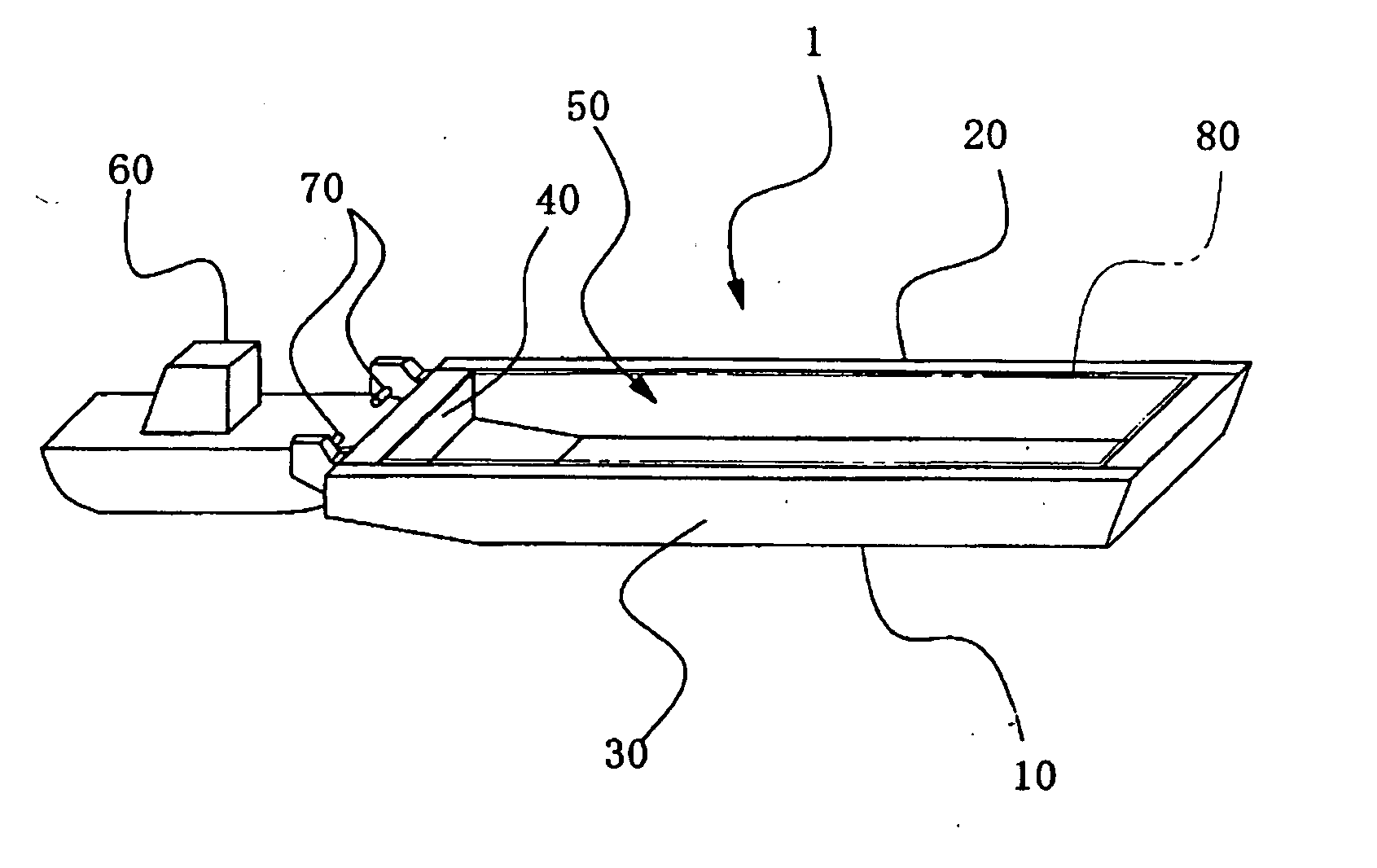
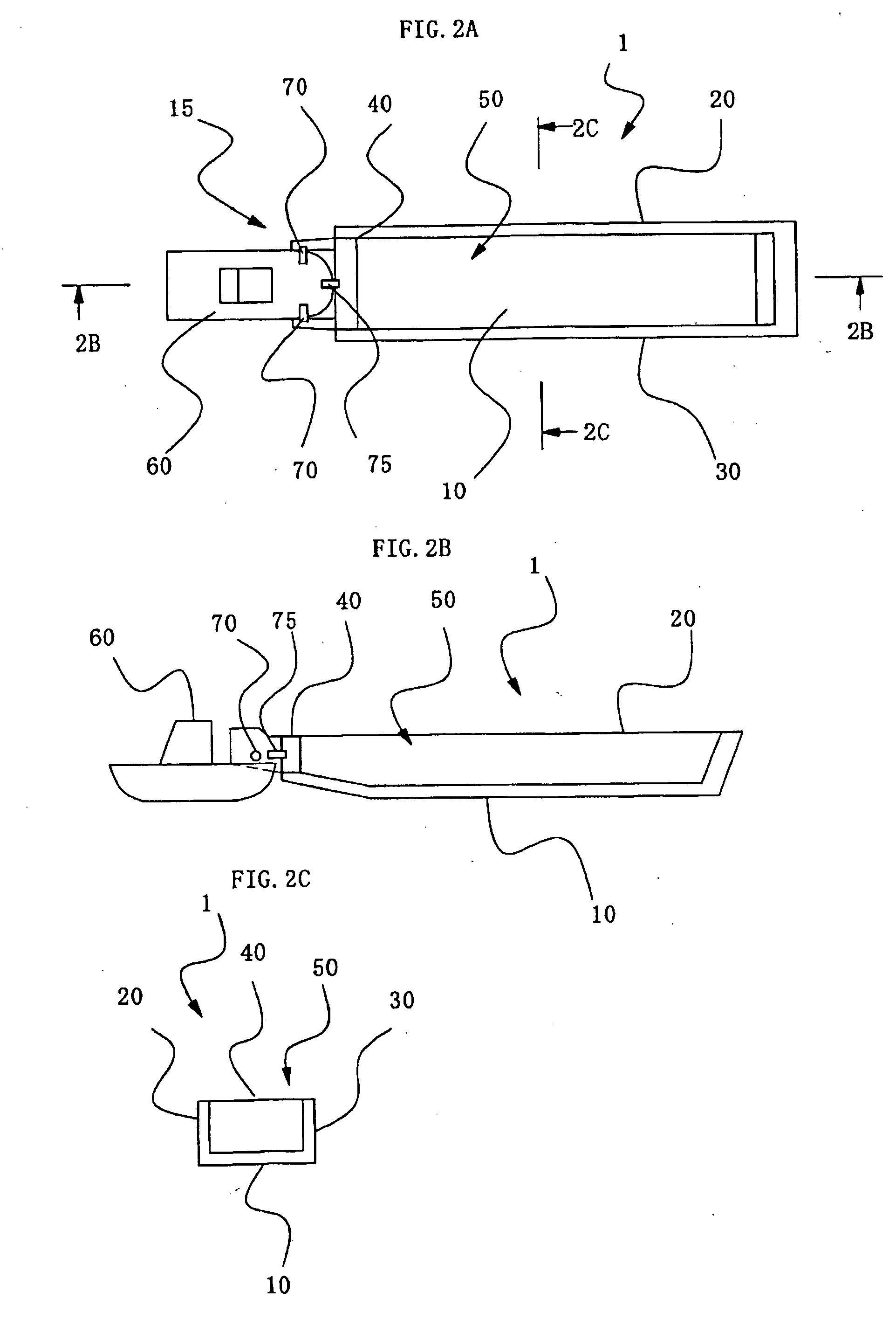
[0032]FIG. 1 illustrates the floating structure that lies in one execution form of this invention, FIG. 2A illustrates a plan of the floating structure that lies in one execution form of this invention, FIG. 2B illustrates a longitudinal section of the floating structure that lies in FIG. 2A, FIG. 2C illustrates a cross sectional side view of the floating structure that lies in FIG. 2A. Floating structure 1 that lies this invention as shown in FIGS. 1,2A,2B,2C, possesses the hull structure made of steel that can endure hydraulic pressure under the water line, and gives necessary rust prevention painting, etc. This floating structure 1 has central tank 10 where a front wall and the bottom of a structure are composed, wing tank 20 where a left wall is composed, wing tank 30 where a right wall is composed, and gate 40 that composes a rear wall.

[0033]Central tank 10 has the floating body of the abbreviation box shape of the size of extent in which the oil tanker and oil barge of single ...


PUM


Abstract

This invention is to offer the floating structure to change oil tanker and oil barge of single hull into that of double hull by simple method. This floating structure is provided with central tanks, wing tanks on right and left of central tank and gate at the end of the floating structure. This floating structure can change the oil tanker or oil barge of the single hull to double hull by leading-in and fixing oil tanker or oil barge of single hull in concave portion formed between the central tanks, wing tanks and the gate. The gate has the connecting coupler with tugboat.

Description

BACKGROUND OF THE INVENTION[0001]1. Field of the Invention[0002]The present invention relates to a floating structure which is used in the river and the ocean.[0003]2. Description of Related Art[0004]The oil tanker and the oil barge of the single hull have the cargo oil tanks directly facing to the outside by a partitioned steel wall at its bottom and side. (Hereafter, it is said “single hull”). However, the loaded cargo oil flows out from the damage part of cargo tank when damage to which single hull tears in some causes of the collision, grounding, corrosion, and breakage, etc. is received, and oil will pollute the river and the ocean.[0005]Therefore, cargo oil is obligated to be loaded inside of double skin of the oil tanker and the oil barge when transporting at sea (Hereafter, it is said “double hull”) by the international agreement (International Convention for the Prevention of Pollution from Ships, 1973 and Protocol of 1978).[0006]On the other hand, it is internationally ope...

Claims


Application Information

Patent Timeline
IPC IPC(8): B63B35/40
CPCB63B35/40
Inventor SADAKUNI, KENJI
Owner TAISEI ENG CONSULTANTS
Why Eureka
Try Eureka