
Wireless microphone device

a microphone and wireless technology, applied in the field of wireless microphone devices, can solve problems such as user discomfort, reduce the possibility of radio wave being sheltered or absorbed by the human body, and reduce the possibility of user discomfor

Inactive Publication Date: 2011-03-10
TAIWAN GOMET TECH
View PDF1 Cites 2 Cited by
  • Summary
  • Abstract
  • Description
  • Claims
  • Application Information

AI Technical Summary

Benefits of technology

[0004]In view of the drawbacks of the prior art, a primary object of the present invention is to provide a wireless microphone device for solving the condition that the conventional antenna element is easily bended and fractured by the user's body.
[0006]As described above, the wireless microphone device of the present invention may comprise one or more following advantages:
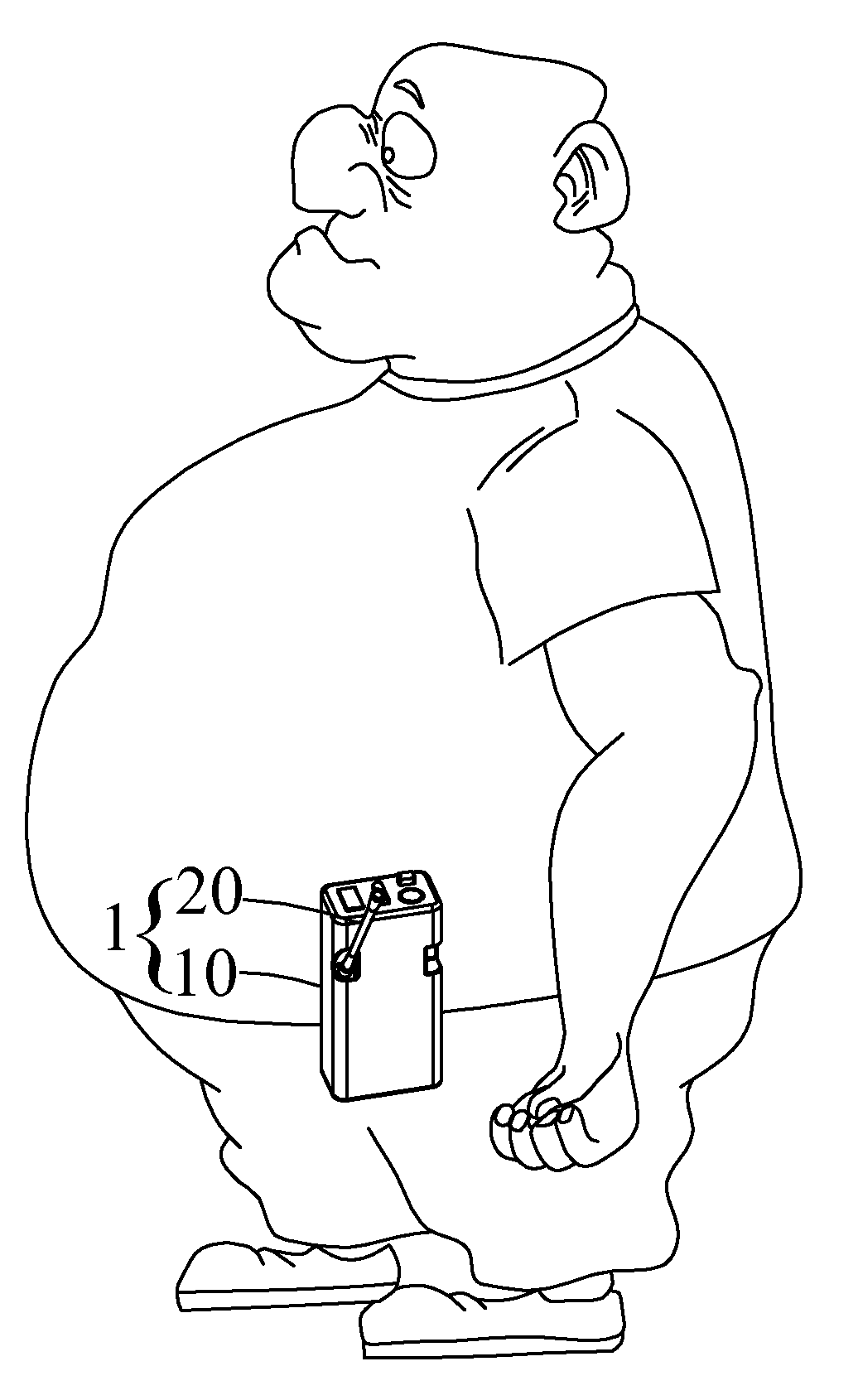
[0007](1). An oblique angle is formed between the antenna element and the side surface of the wireless microphone device, thereby preventing the antenna element from pressing against the user's body and causing uncomfortable feelings of the user while wearing the wireless microphone device.
[0008](2). Because the antenna element is obliquely disposed on the wireless microphone device, the user's body pressing on the antenna element can be avoided and thus reducing deformation of the antenna element. On the other hand, the obliquely disposed antenna element keeps a distance from the user's body, and thereby the possibility of the radio wave being sheltered or absorbed by the human body is reduced.

Problems solved by technology

An oblique angle is formed between the antenna element and the side surface of the wireless microphone device, thereby preventing the antenna element from pressing against the user's body and causing uncomfortable feelings of the user while wearing the wireless microphone device.

Method used


Image

  • Wireless microphone device
  • Wireless microphone device
  • Wireless microphone device

Examples


Embodiment Construction

[0015]Referring to FIG. 3 and FIG. 4 for a schematic view and a lateral view of the wireless microphone respectively, the wireless microphone device 1 comprises a casing 10 and an antenna element 20. A concave recession 12 is disposed on a side surface 11 of the casing 10. One end of the antenna element 10 is disposed on the bottom surface 13 of the concave recession 12 and the antenna element 10 is extending upwardly with an oblique angle θ relative to the side surface 11. A transceiver 14 is disposed inside the casing, and the transceiver 14 transmits or receives a microphone signal by the antenna element 10.

[0016]In addition, the antenna element 20 has a fastening portion 21 and an extending portion 22. The antenna element 20 may be mounted to the casing 10 by latching, screwing or inserting the fastening portion 21 to the bottom surface 13. Other measures may also be taken to fix the fastening portion 21 to the bottom surface 13. Furthermore, one end of the extending portion 22 ...


PUM


Abstract

The present invention provides a wireless microphone device which comprises a casing, an antenna element and a transceiver. A concave recession is formed on a side surface of the casing. One end of the antenna element is disposed on a bottom surface of the concave recession, and the other end of the antenna element is extending upwardly with an oblique angle relative to the side surface. The transceiver is disposed inside the casing, and transmits or receives a microphone signal by the antenna element. Consequently, according to the present invention, the wireless microphone with the obliquely disposed antenna element can avoid the radio wave from being blocked or absorbed by a user's body, and thereby the efficiency of the antenna element receiving or transmitting the radio wave would not be reduced.

Description

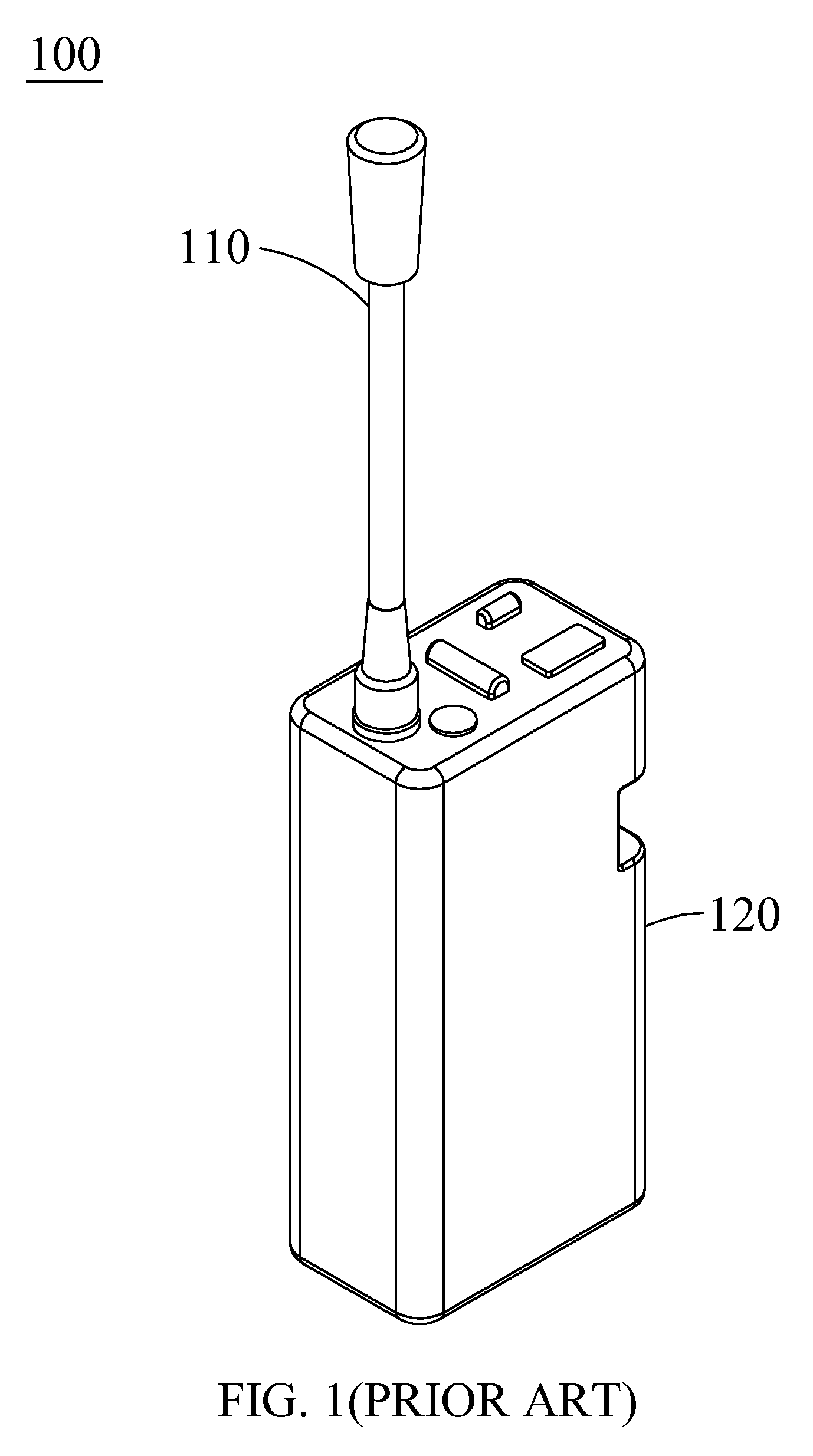
FIELD OF THE INVENTION[0001]The present invention relates to a wireless microphone device, and more particular to a wireless microphone device having an obliquely disposed antenna element.BACKGROUND OF THE INVENTION[0002]Conventional belt pack wireless microphones can be utilized to communicate with others without the necessity of holding the microphone by hands, and thus provides the availability of the hands to perform other tasks. Referring to FIG. 1 for a schematic view of conventional wireless microphone device, the antenna element 110 is usually disposed on the top surface of the casing 120 of the wireless microphone device 100 for receiving or transmitting the radio signal. One end of the antenna element 110 is fixed on the top surface of the casing 120, and the other end is extending upwardly and vertically with a predetermined length.[0003]Referring to FIG. 2 for a diagram of a user wearing the conventional wireless microphone device around the waist, the antenna element 11...

Claims


Application Information

Patent Timeline
IPC IPC(8): H04R3/00H04R19/04
CPCH04R2420/07H04R1/08
Inventor CHANG, SHENG-HSIUNGCHANG, SHENG-YUAN
Owner TAIWAN GOMET TECH
Learn More