X-ray analysis apparatus and x-ray analysis method

Active Publication Date: 2011-03-03
HITACHI HIGH TECH SCI CORP
View PDF8 Cites 20 Cited by
  • Summary
  • Abstract
  • Description
  • Claims
  • Application Information

AI Technical Summary

Benefits of technology

[0008]In view of such problems as described above, it is an object of the invention to provide an X-ray analysis apparatus and an X-ray analysis method which allow sample measurement safely with high working efficiency.
[0009]In order to solve the above-described problem, the invention employs a configuration and a method described below. In other words, an X-ray analysis apparatus according to the invention includes a radiation source configured to irradiate an irradiation point on a sample with radiation; an X-ray detector configured to detect a characteristic X-ray and a scattered X-ray emitted from the sample and output a signal including energy information about the characteristic X-ray and the scattered X-ray; an analyzer configured to analyze the signal; a sample stage configured to place the sample thereon; a shifting mechanism being capable of relatively shifting the sample on the sample stage and the radiation source and the X-ray detector with respect to each other; a height measuring mechanism being capable of measuring the height of the irradiation point on the sample; and a controller configured to control the shifting mechanism on the basis of the measured height of the irradiation point on the sample and adjust the distance of the sample with respect to the radiation source and the X-ray detector. Accordingly, the height of the sample can be grasped accurately, and the distance of the sample on the sample stage with respect to the radiation source and the X-ray detector can be adjusted.
[0012]The X-ray analysis apparatus according to the invention is characterized in that the optical axis of the radiation irradiated from the radiation source is coaxial with the optical axis of the laser displacement sensor, and the sample is irradiated with the radiation and a laser emitted from the laser displacement sensor. Accordingly, even when the sample has concavity and convexity, the laser can be delivered to the position to be irradiated with radiation, so that the height of the position to be irradiated with radiation can be measured accurately.
[0015]The X-ray analysis apparatus according to the invention includes a mirror configured to align the optical axis of the laser displacement sensor in coaxial with the optical axis of the radiation, and a beam splitter configured to align the optical axis of the radiation, the optical axis of the laser displacement sensor, and the optical axis of the sample observation system in coaxial with each other. Accordingly, the three optical axes are aligned coaxially, and hence a compact apparatus which can save the space of installation is obtained.
[0019]The X-ray analysis method according to the invention includes a step of measuring the height of the irradiation point on the sample by the height measuring mechanism; and a step of conducting measurement and analysis by delivering radiation at the height of the irradiation point on the sample, and is characterized in that the step of conducting measurement and analysis includes correcting parameters used in calculation according to the difference between a standard position of irradiation of the radiation and the heightwise position of the irradiation point when performing the calculation for a quantitative analysis from data obtained by the analyzer. Accordingly, an accurate quantitative analysis is achieved.
[0020]According to the invention, following advantages are achieved. By grasping the height of the sample accurately by the height measuring mechanism and adjusting the distance of the sample with respect to the radiation source and the X-ray detector by the controller, sample measurement is achieved safely with high working efficiency.

Problems solved by technology

The technology in the related art still has the following problems.
In addition, since the revolver is revolved for switching the objective lens, the operation efficiency is not good.
When measuring a sample having significant concavity and convexity, there is a risk of collision of the sample with the objective lens.

Method used


Image

  • X-ray analysis apparatus and x-ray analysis method
  • X-ray analysis apparatus and x-ray analysis method
  • X-ray analysis apparatus and x-ray analysis method

Examples


Embodiment Construction

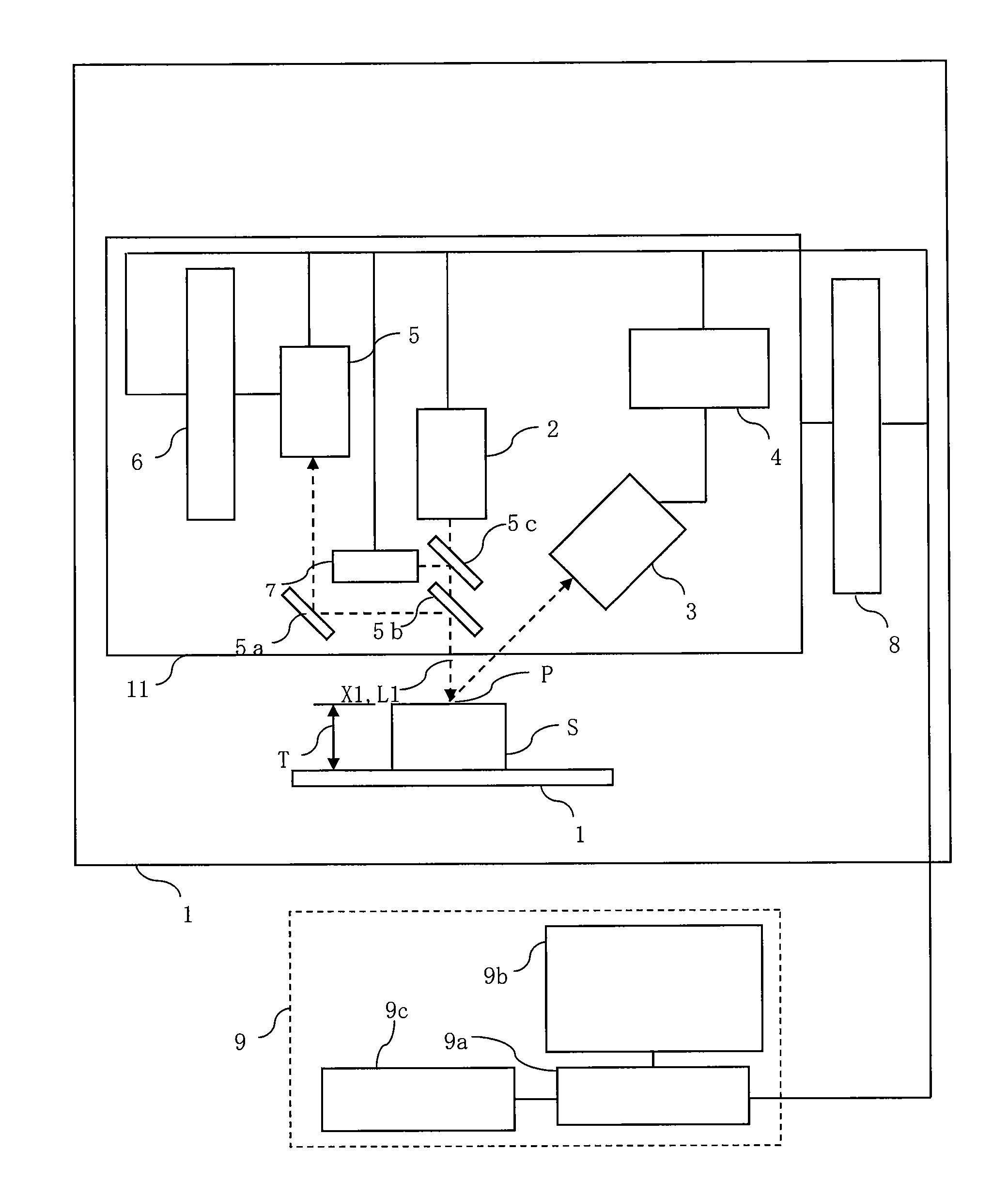
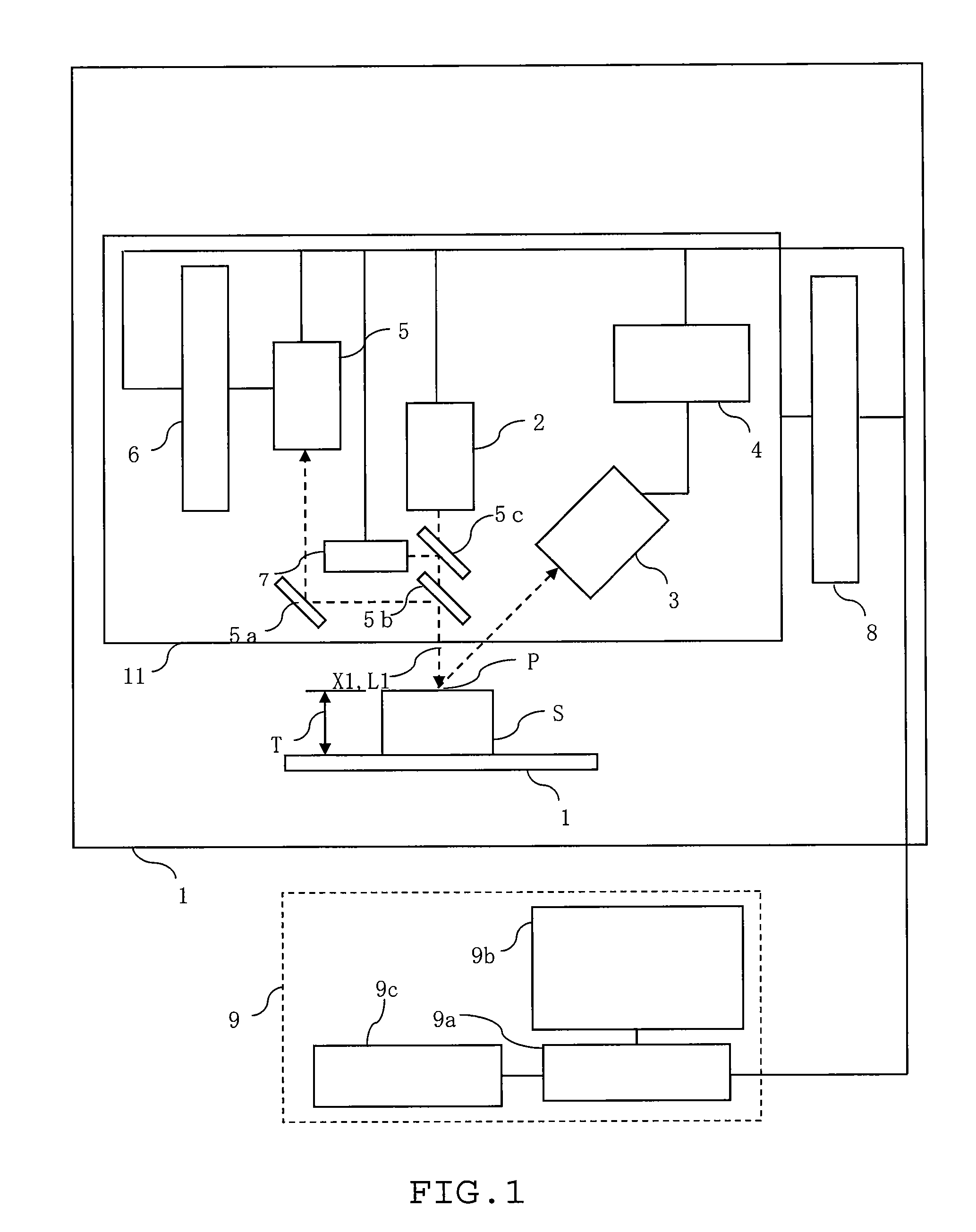
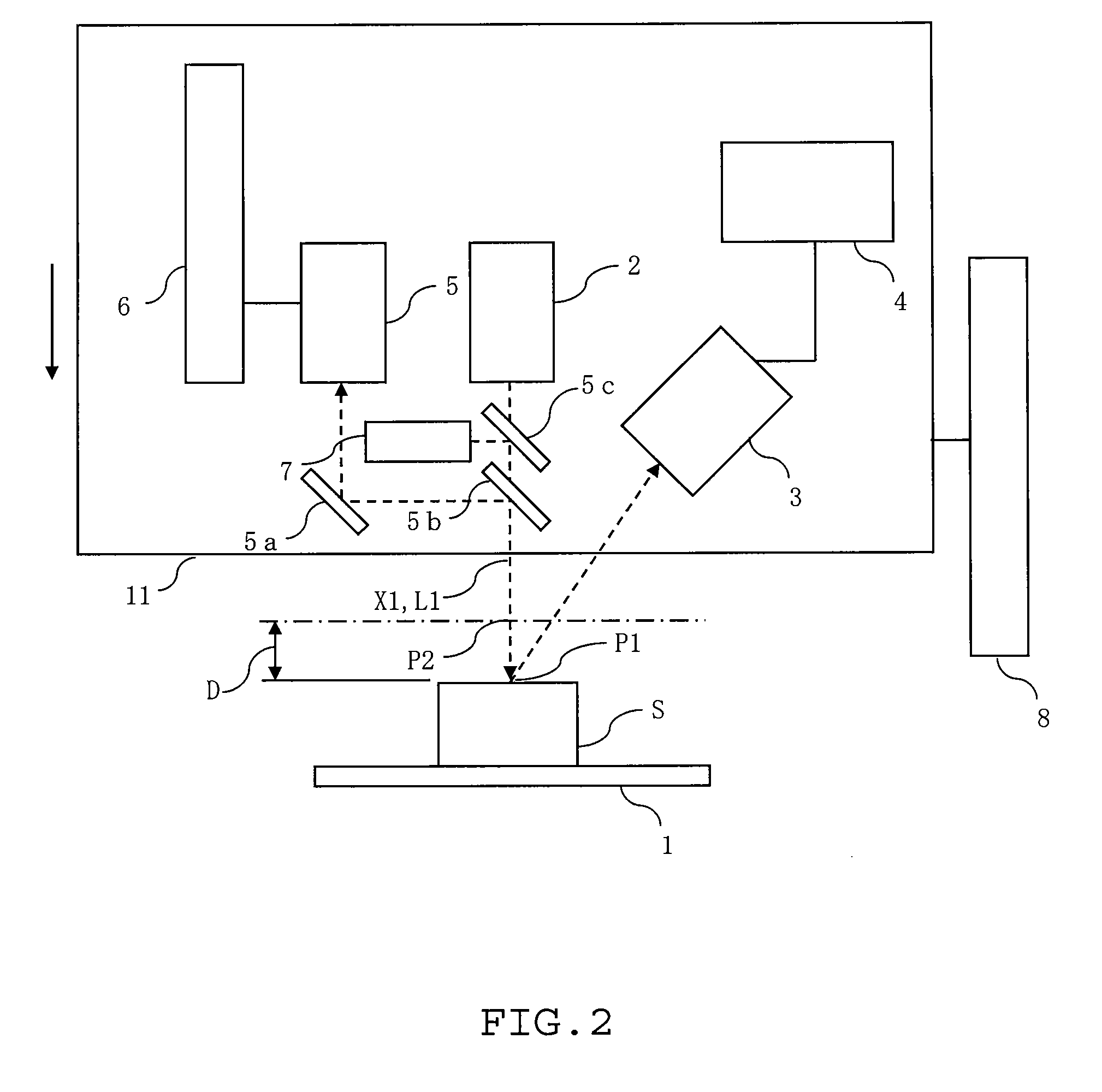
[0025]Referring now to FIG. 1 to FIG. 4, an embodiment of an X-ray analysis apparatus and an X-ray analysis method according to the invention will be described. In the respective drawings used in the description given below, the contraction scale is changed as needed in order to illustrate respective members in recognizable sizes.

[0026]The X-ray analysis apparatus in this embodiment is, for example, an energy dispersive fluorescence X-ray analysis apparatus and, as shown in FIG. 1, includes a sample stage 1 configured to be movable with a sample S placed thereon, an X-ray tube (radiation source) 2 configured to irradiate a given irradiation point P1 on the sample S with a primary X-ray (radial ray) X1, an X-ray detector 3 configured to detect a characteristic X-ray and a scattered X-ray emitted from the sample S and output a signal including energy information about the characteristic X-ray and the scattered X-ray, an analyzer 4 connected to the X-ray detector 3 and configured to an...


PUM


Abstract

An X-ray analysis apparatus including: a radiation source configured to irradiate an irradiation point on a sample with radiation; an X-ray detector configured to detect a characteristic X-ray emitted from the sample, and output a signal including energy information about the characteristic X-ray; an analyzer configured to analyze the signal; a sample stage configured to allow placement of the sample thereon; a shifting mechanism being capable of relatively shifting the sample on the sample stage and the radiation source and the X-ray detector with respect to each other; a height measuring mechanism being capable of measuring the height of the irradiation point on the sample; and a controller configured to control the shifting mechanism on the basis of the measured height of the irradiation point on the sample and adjust the distance of the sample with respect to the radiation source and the X-ray detector is used.

Description

RELATED APPLICATIONS[0001]This application claims priority under 35 U.S.C. §119 to Japanese Patent Application No. 2009-198718 filed on Aug. 28, 2009, the entire content of which is hereby incorporated by reference.BACKGROUND OF THE INVENTION[0002]1. Technical Field[0003]The present invention relates to an X-ray analysis apparatus and an X-ray analysis method for analyzing a fluorescence X-ray generated from a sample surface.[0004]2. Description of the Related Art[0005]A fluorescence X-ray analysis is performed by irradiating a sample with an X-ray emitted from an X-ray source, detecting a fluorescence X-ray, which is a characteristic X-ray emitted from the sample, with an X-ray detector, then obtaining a spectrum from energy detected therefrom, and then conducting a qualitative analysis or a quantitative analysis on the sample. The fluorescence X-ray analysis allows a non-destructive and rapid analysis on the sample, and hence is widely used in manufacturing processes or in quality...

Claims


Application Information

Patent Timeline
IPC IPC(8): G01N23/201
CPCG01N2223/076G01N23/223G01B11/14
Inventor TAKAHARA, TOSHIYUKI
Owner HITACHI HIGH TECH SCI CORP
Why Eureka
Try Eureka