
Measurement and adjustment of real-time values according to residence time in networking equipment without access to real time

Inactive Publication Date: 2011-03-03
SEMTECH CORP
View PDF7 Cites 105 Cited by
  • Summary
  • Abstract
  • Description
  • Claims
  • Application Information

AI Technical Summary

Benefits of technology

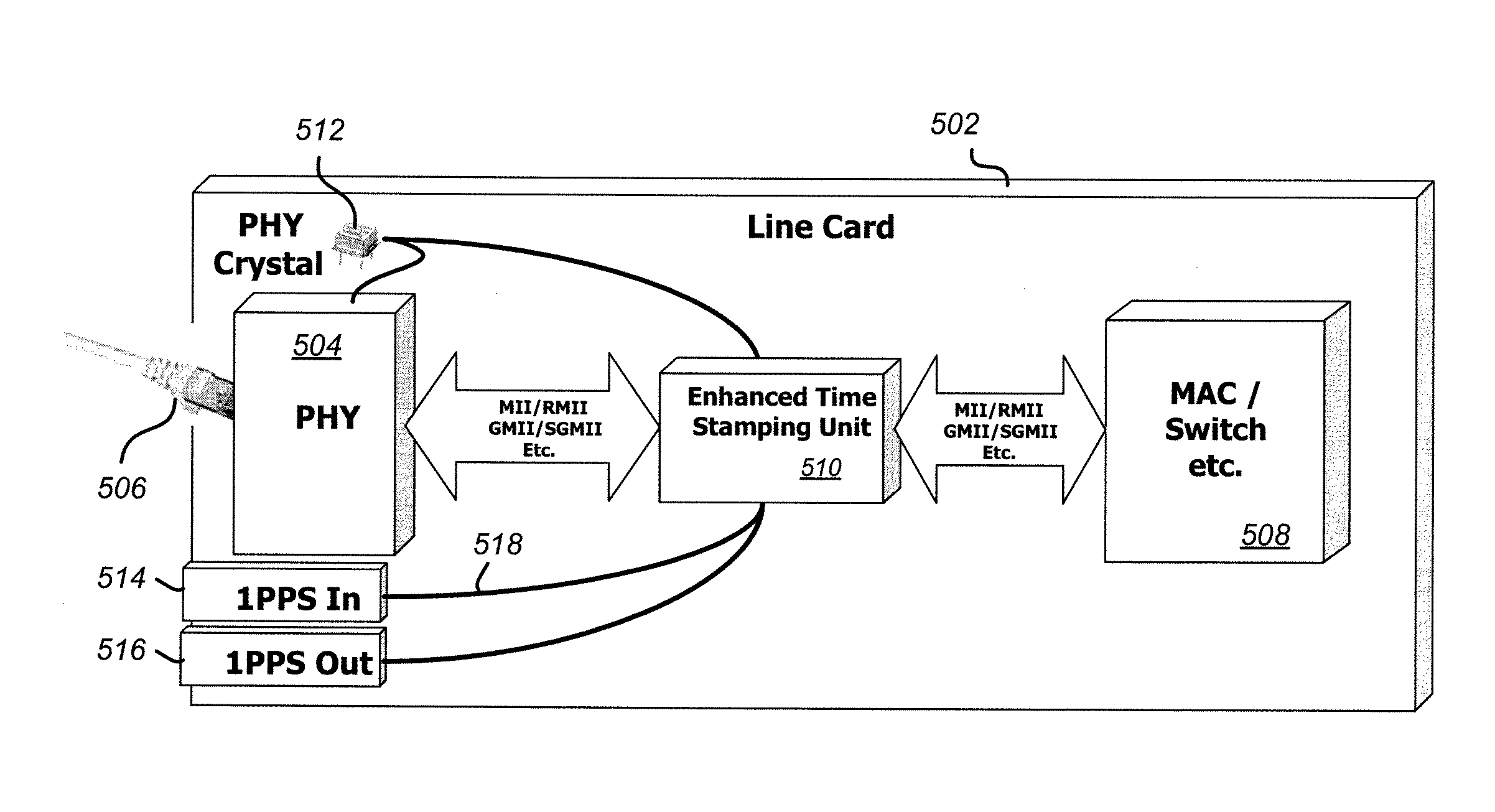
[0010]The invention provides a system and method for implementing PTP transparent clocks in a distributed network in a manner that is readily applicable to both new designs and retrofit designs. A nominally 1-pulse-per-second (1-pps) timing signal is routed from a timing pulse generator to each network element using a dedicated pulse distribution network. Local oscillators at each network element are locked to this 1-pps reference, such that the 1-pps reference provides accuracy and stability to local clocks associated with each network element.
[0015]In other embodiments of a clock synchronization system in accordance with the present invention, the timing pulse generator includes a variable phase delay element. In one embodiment, the programmable phase delay element can be programmed to adjust the timing pulse phase by + / −16 ns or more. Of course, other programmable phase delays are possible and would similarly fall within the scope and spirit of the present invention. The programmable delay allows for compensation of routing delays between the timing pulse generator and the time stamping units within the distributed network elements.

Problems solved by technology

A drawback of such a distribution scheme is that the dedicated clock management and distribution hardware performs only this individual function and consumes a significant fraction of the resources and cost of running a network.
But Ethernet is an inherently asynchronous protocol, posing significant challenges to using it as a basis for precise timing control.
Indeed, NTP is prone to traffic-dependent latencies and timing jitter that tend to limit its accuracy to several milliseconds.
While the precision time stamping removes much of the timing uncertainty and skew within the network, packet delay variation through network elements such as switches and routers can degrade timing performance by introducing load-dependent delays and asymmetries in the forward and reverse timing paths.
However, the implementation of transparent clocks is very complex.
Accurate time of day (ToD) is generally required at all of the network elements but is not always available.

Method used


Image

  • Measurement and adjustment of real-time values according to residence time in networking equipment without access to real time
  • Measurement and adjustment of real-time values according to residence time in networking equipment without access to real time
  • Measurement and adjustment of real-time values according to residence time in networking equipment without access to real time

Examples


Embodiment Construction

[0028]The invention provides an apparatus and method for improving PTP time recovery in packet-switched networks that can be readily applied to existing Ethernet networks. FIG. 1 depicts a typical system providing packet synchronization over a packet network using IEEE-1588. A master unit 102 may be implemented as a ToPSync unit configured to act as a master device. As such, it may receive an input from a Coordinated Universal Time (UTC) reference 110 that delivers precision real time. The UTC unit 110 may comprise a global positioning system (GPS) receiver or similar device. A master timing unit has an internal timebase driven by its own local oscillator 112. The master unit aligns its timebase with the UTC reference 110 such that it generates time-stamped time-synchronization packets that are distributed via packet network 104 to one or more slave devices 106 and 108. In one implementation, the master unit may be a ToPSync module. However, the invention is equally applicable to ot...


PUM


Abstract

A system and method of synchronizing clocks in a distributed network is disclosed. A simple 1-pulse-per-second timing pulse is routed to time-stamping units in each network device and utilized to measure traffic-dependent synchronization packet residence delays within network elements. Synchronization messages are updated to reflect the measured residence times, thus creating transparent clocks that can readily be synchronized across the network. The simple timing pulse architecture allows the method to be applied readily both to new designs and to retrofit existing hardware.

Description

RELATED APPLICATIONS[0001]This application claims the benefit under 35 U.S.C. §119(e) of U.S. Provisional Application No. 61 / 236,799, filed Aug. 25, 2009.BACKGROUND OF THE INVENTION[0002]1. Field of the Invention[0003]The present invention relates to the field of synchronizing time clocks between distributed network elements, and more particularly, to adjusting packet time stamps by measuring packet residence times in network elements without access to real-time clocks.[0004]2. Description of Related Art[0005]Synchronizing the elements that make up a network is fundamentally important to achieving good network performance. At a basic level, synchronizing distributed clocks requires distributing timing information from a master clock to a number of slave clocks throughout the network. A number of schemes are employed in practice. For example, each network element may include its own real-time clock; synchronized to a master reference via synchronization signals. Dedicated electronic ...

Claims


Application Information

Patent Timeline
IPC IPC(8): H04J3/06
CPCH04J3/0667H04J3/0697H04J3/0673
Inventor LANSDOWNE, RICHARD JAMES
Owner SEMTECH CORP
Learn More