
Multi-type wind turbine

Active Publication Date: 2013-05-23
DOOSAN HEAVY IND & CONSTR CO LTD
View PDF23 Cites 37 Cited by
  • Summary
  • Abstract
  • Description
  • Claims
  • Application Information

AI Technical Summary

Benefits of technology

The present invention relates to a multi-type wind turbine with several types of wind turbines that work together to improve stability, reduce noise, and minimize fatigue loads. The wind turbine also has a sufficient gap between the blade and tower, which enhances its stability and reliability. Additionally, the wind turbine reduces energy consumption by controlling the angle of the blade based on wind conditions and improves aerodynamic performance by increasing the amount of energy production and reducing the noise caused by the rotating blade.

Problems solved by technology

Due to this, the installation and maintenance cost increases by geometric progression, thereby resulting in a problem of causing a significant obstacle in the broad distribution of wind turbines due to an increase of technical degree of difficulty and cost.
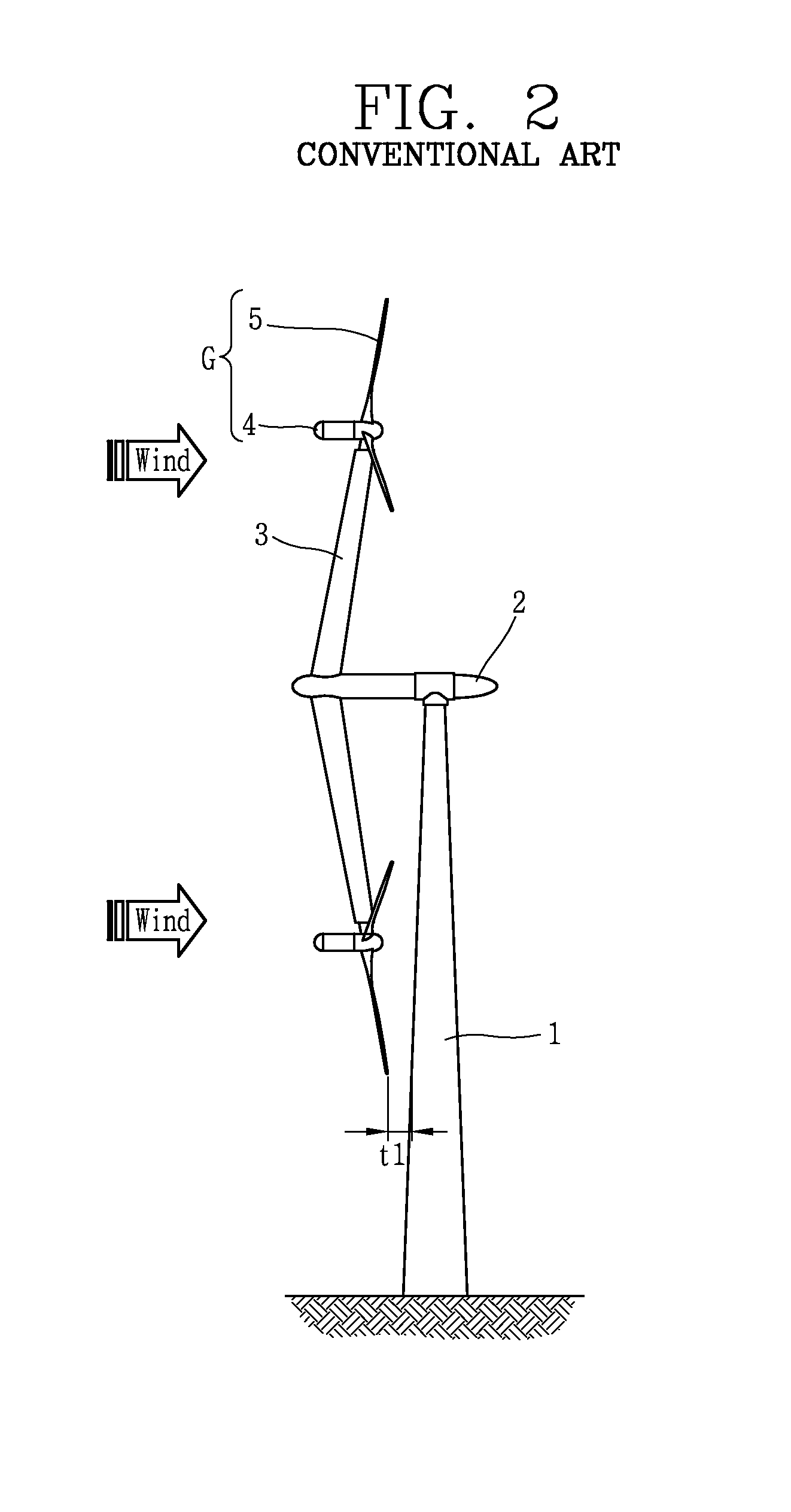
However, though having the above advantages, according to the forgoing multi-type wind turbine in the related art, as the support arm 3 is rotated with respect to the main nacelle 2, the variation of wind speed is terrible, the noise is aggravated, and the fatigue load of a system is increased as well as the structural strength of the support arm 3 is weakened, thereby resulting in a problem that it cannot be applicable to a large capacity of unit generator (G).
Furthermore, according to a multi-type wind turbine in the related art, each unit generator (G) is disposed in a downwind format at a front surface of the tower 1 and thus it may be difficult to maintain a gap (t1) between a blade edge of each blade 5 and the tower 1, thereby resulting in that the blade 5 can be damaged and collided with the tower 1.
In addition, according to a multi-type wind turbine in the related art, the weight of one blade is significant and thus a lot of energy should be consumed to control the angle of each blade according to the wind conditions as well as the reaction speed is slow, and the aerodynamic performance is decreased to reduce the amount of energy production as the vicinity of a blade root is formed in a cylindrical shape, and the speed at a blade edge should be increased in order to enhance the amount of energy production, thereby increasing the noise.

Method used


Image

  • Multi-type wind turbine
  • Multi-type wind turbine
  • Multi-type wind turbine

Examples


Embodiment Construction

[0058]Hereinafter, a multi-type wind turbine according to the present disclosure will be described in detail based on an embodiment illustrated in the accompanying drawings.

[0059]FIG. 3 is a perspective view illustrating an example of a multi-type wind turbine according to the present disclosure, and FIGS. 4 and 5 are a side view and a front view illustrating a wind turbine according to FIG. 3.

[0060]As illustrated in the drawings, a multi-type wind turbine according to the present disclosure may include a tower 10 raised up and installed from the ground at a predetermined height, and a plurality of unit generators (G) arranged in a radial direction around an upper end of the tower 10 to generate electricity individually while being rotated with different directions or different rotation speeds by a wind speed. The unit generator (G) may include a sub-nacelle 40 which will be described later and a plurality of blades 50 combined with the sub-nacelle 40.

[0061]The tower 10 may be forme...


PUM


Abstract

The present disclosure relates to a multi-type wind turbine. The present disclosure may be configured such that a plurality of arms are combined with one tower in a radial direction, and a unit generator having a blade is provided at the plurality of arms, respectively, and at least two of the unit generators are rotated in opposite directions to each other. Furthermore, both ends of the arm may be located both sides thereof on the basis of the height directional central line of the tower to be fixed thereto or both ends of the arm may be located at one side of the tower to be rotatably combined therewith. Furthermore, the rotation speed and tilt angle of the blade of the unit generator may controlled in an individual manner or controlled in a grouped manner. Furthermore, the unit generator may include a main blade and a sub-blade which is smaller than the main blade.

Description

CROSS-REFERENCE TO RELATED APPLICATIONS[0001]The present disclosure relates to subject matters contained in priority Korean Application No. 10-2011-0120372, filed on Nov. 17, 2011, Korean Application No. 10-2011-0134749, filed on Dec. 14, 2011 and Korean Application No. 10-2012-0118594, filed on Oct. 24, 2012, which are herein expressly incorporated by references in its entirety.BACKGROUND OF THE INVENTION[0002]1. Field of the Invention[0003]The present disclosure relates to a multi-type wind turbine having a plurality of unit generators in one tower.[0004]2. Description of the Related Art[0005]Wind power generation refers to a generation method of converting energy generated by wind into mechanical energy (rotational force) through a spindle using a windmill, and allowing the mechanical energy to drive a generator, thereby obtaining electrical power converted into electrical energy.[0006]Wind power generation has the highest economic efficiency among energy sources that have been d...

Claims


Application Information

Patent Timeline
IPC IPC(8): F03D9/00
CPCF03D9/002F03D1/02Y02E10/726Y02E10/721Y02E10/725F03D1/025F03D9/25F03D13/20F03D80/00Y02E10/72Y02E10/728
Inventor LEE, KI HAKLEE, SANG ILPARK, JONG PO
Owner DOOSAN HEAVY IND & CONSTR CO LTD
Learn More