
Vision System for Monitoring Humans in Dynamic Environments

a dynamic environment and vision system technology, applied in the field of vision monitoring systems for tracking humans, to achieve the effect of improving work cell activity efficiency and productivity, and improving productivity

Active Publication Date: 2011-03-03
GM GLOBAL TECH OPERATIONS LLC
View PDF5 Cites 108 Cited by
  • Summary
  • Abstract
  • Description
  • Claims
  • Application Information

AI Technical Summary

Benefits of technology

[0005]An advantage of an embodiment of the invention provides for cognitive monitoring of humans in a manufacturing and assembly environment for enhancing the safety of workers and production efficiency. The system uses an automated visual supervision of human-to-machine interaction that does not depend on physical fences and guarding devices. The system enables a natural and intuitive interaction around moving equipment without the use of personal protective equipment. The effective monitoring of people and automation equipment improves factory processes by enabling virtual reconfigurable three dimensional fences around the automated equipment that can trigger warnings, slow down, speed up or shutdown the automated equipment dependent upon a predicted path of travel within the monitored area. This “virtual guarding” capability can reduce manufacturing process configuration / conversion times and reduce the amount of unused space around the automated equipment. While not explicitly described in detail, this capability is just as useful in non-manufacturing sectors where people and other types of systems interact where automated supervision of the interaction is desired. Some examples would be human interaction with transportation systems and amusement ride loading, interaction with automated material handling systems and enforcement of the flow and location of people for retail, tours, restricted access or for security reasons.
[0008]A variation of the safety monitoring capability of this system is monitoring restricted areas that may have significant and possibly hazardous automated or other equipment activity that only requires periodic service or access. This system would monitor the integrity of access controls to such areas and trigger alerts due to unauthorized access. Since service or routine maintenance in this area may be needed on off shifts or other downtime, the system would monitor authorized access and operations of a person (or persons) and would trigger alerts locally and with a remote monitoring station if activity unexpectedly stops due to accident or medical emergency. This capability could improve productivity for these types of tasks where the system could be considered part of a “buddy system” for the purposes of personal safety.
[0009]This system also has the capability to be applied in applications where the activities of people in an area are tracked and the motion and activity is logged. This is useful in the automated time and motion study of activities that can be used to monitor performance and provide date for use in improving work cell activity efficiency and productivity. This capability can also enable activity monitoring within a prescribed sequence where deviations in the sequence can be identified, logged and alerts can be generated for the detection of human task errors. This “error proofing” capability can be utilized to prevent task errors from propagating to downstream operations and causing quality and productivity problems due to mistakes in sequence or proper material selection for the prescribed task.

Problems solved by technology

This system would monitor the integrity of access controls to such areas and trigger alerts due to unauthorized access.

Method used


Image

  • Vision System for Monitoring Humans in Dynamic Environments
  • Vision System for Monitoring Humans in Dynamic Environments
  • Vision System for Monitoring Humans in Dynamic Environments

Examples


Embodiment Construction

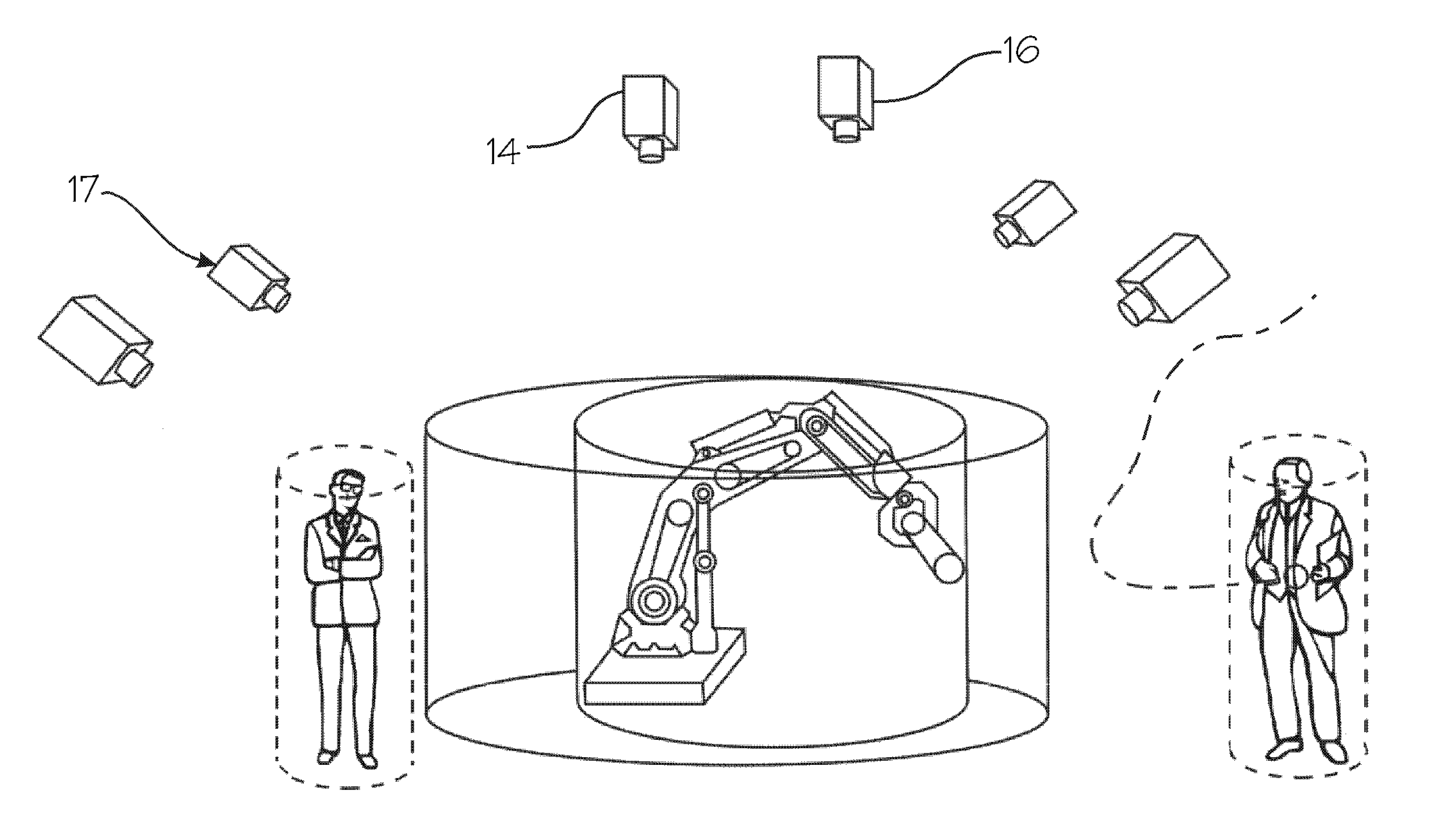
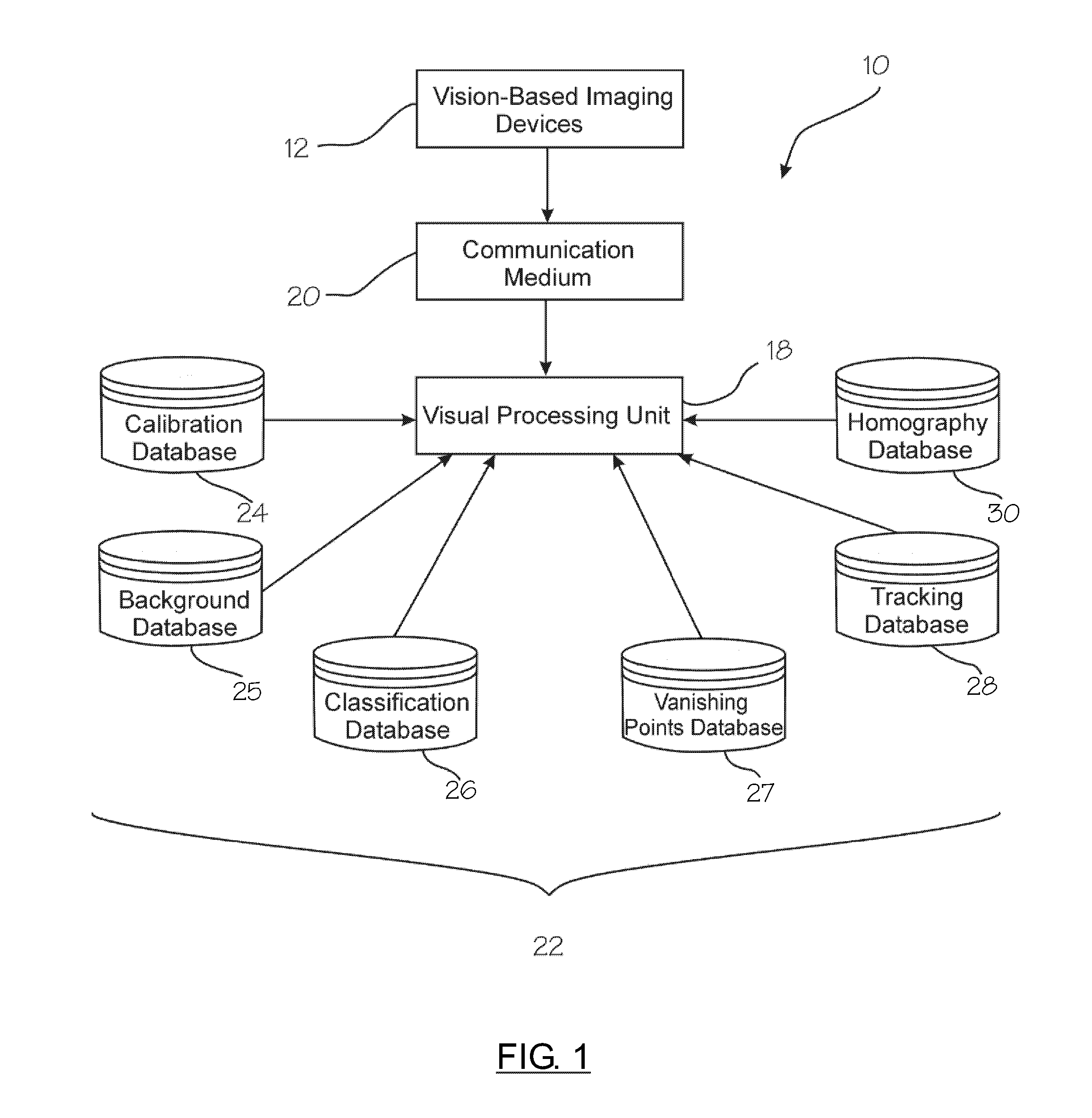
[0020]There is shown in FIG. 1, generally at 10, a block diagram of a safety monitoring system for monitoring a workspace area of an assembly, manufacturing, or like process. The safety monitoring system 10 includes a plurality of vision-based imaging devices 12 for capturing visual images of a designated workspace area. The plurality of vision-based imaging devices 12, as illustrated in FIG. 2, is positioned at various locations and elevations surrounding the automated moveable equipment. Preferably, wide-angle lenses or similar wide field of view devices are used to visually cover more workspace area. Each of the vision-based imaging devices are substantially offset from one another for capturing an image of the workspace area from a respective viewpoint that is substantially different from the other respective imaging devices. This allows various streaming video images to be captured from different viewpoints about the workspace area for distinguishing a person from the surroundi...


PUM


Abstract

A safety monitoring system for a workspace area. The workspace area related to a region having automated moveable equipment. A plurality of vision-based imaging devices capturing time-synchronized image data of the workspace area. Each vision-based imaging device repeatedly capturing a time synchronized image of the workspace area from a respective viewpoint that is substantially different from the other respective vision-based imaging devices. A visual processing unit for analyzing the time-synchronized image data. The visual processing unit processes the captured image data for identifying a human from a non-human object within the workspace area. The visual processing unit further determining potential interactions between a human and the automated moveable equipment. The visual processing unit further generating control signals for enabling dynamic reconfiguration of the automated moveable equipment based on the potential interactions between the human and the automated moveable equipment in the workspace area.

Description

BACKGROUND OF INVENTION[0001]An embodiment relates generally to vision monitoring systems for tracking humans.[0002]Manufacturing and assembly operations employ the use of safety devices to prevent harm to an operator working in the vicinity of the equipment. A plurality of sensors and other devices are disposed throughout a manufacturing or assembly process for sensing the operator's proximity to the equipment. In response to the operator being within a predetermined distance from the equipment, the equipment is shut down or prevented from executing a task due to the operator being within a caution zone of the equipment. The caution zone is a predefined area or region in which safety concerns are taken into consideration based on proximity of the operator to the equipment where a potential injury to an operator could occur.[0003]The following are examples of safety devices used to detect the operator proximity to the equipment. Floor mats are utilized to sense whether a respective ...

Claims


Application Information

Patent Timeline
IPC IPC(8): H04N7/18
CPCH04N7/181
Inventor WELLS, JAMES W.MENASSA, ROLAND J.WAMPLER, II, CHARLES W.MEDASANI, SWARUPOWECHKO, YURIKIM, KYUNGNAMCHEN, YANG
Owner GM GLOBAL TECH OPERATIONS LLC
Learn More