
Circuits and methods for clock signal duty-cycle correction

a technology of clock signal and duty cycle, applied in the direction of pulse automatic control, pulse manipulation, pulse technique, etc., can solve the problems of affecting the performance of the integrated circuit, affecting the quality of the clock signal while being distributed to the various circuits, and affecting the quality of the clock signal

Active Publication Date: 2011-03-03
MICRON TECH INC
View PDF7 Cites 20 Cited by
  • Summary
  • Abstract
  • Description
  • Claims
  • Application Information

AI Technical Summary

Problems solved by technology

When generating and routing the internal clock signals, however, maintaining the quality of the clock signals while being distributed to the various circuits can present challenges.
An example of a challenge to maintaining the quality of the clock signals is generating internal clock signals while maintaining the duty-cycle of the external clock signals.
Duty-cycle distortion may be process-induced, that is, the device characteristics of the clock generation circuits and clock distribution circuits can shift due to variation in the manufacturing process for the integrated circuit causing the resulting internal clock signal to be distorted.
As a result of the duty-cycle distortion, when generating and distributing the internal clock signal, the various circuits receive a distorted version of the external clock signal.
Due to the duty-cycle distortion, performance of the integrated circuit may be reduced, and in extreme cases, may cause the integrated circuit to function incorrectly.
This approach, however, consumes significant power to drive the circuitry of the differential clock path and requires considerable space to accommodate the parallel clock paths of the differential clock path.
This approach also requires two separate clock paths to distribute the single-ended clock signals and suffers from the same issues as using a differential clock path, that is, significant power consumption and space for the two clock paths.
Although this approach has the benefits of using less power and requiring less space for the clock path in comparison to the previously discussed approaches, as known, distributing a single-ended clock signal and generating an internal differential clock signal from the single-ended clock signal is more susceptible to introducing duty-cycle distortion, such as that related to process-induced distortion.

Method used


Image

  • Circuits and methods for clock signal duty-cycle correction
  • Circuits and methods for clock signal duty-cycle correction
  • Circuits and methods for clock signal duty-cycle correction

Examples


Embodiment Construction

[0012]Certain details are set forth below to provide a sufficient understanding of embodiments of the invention. However, it will be clear to one skilled in the art that embodiments of the invention may be practiced without these particular details. Moreover, the particular embodiments of the present invention described herein are provided by way of example and should not be used to limit the scope of the invention to these particular embodiments. In other instances, well-known circuits, control signals, timing protocols, and software operations have not been shown in detail in order to avoid unnecessarily obscuring the invention.

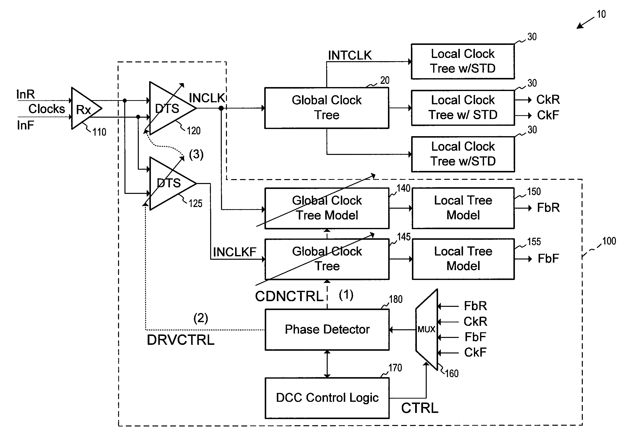
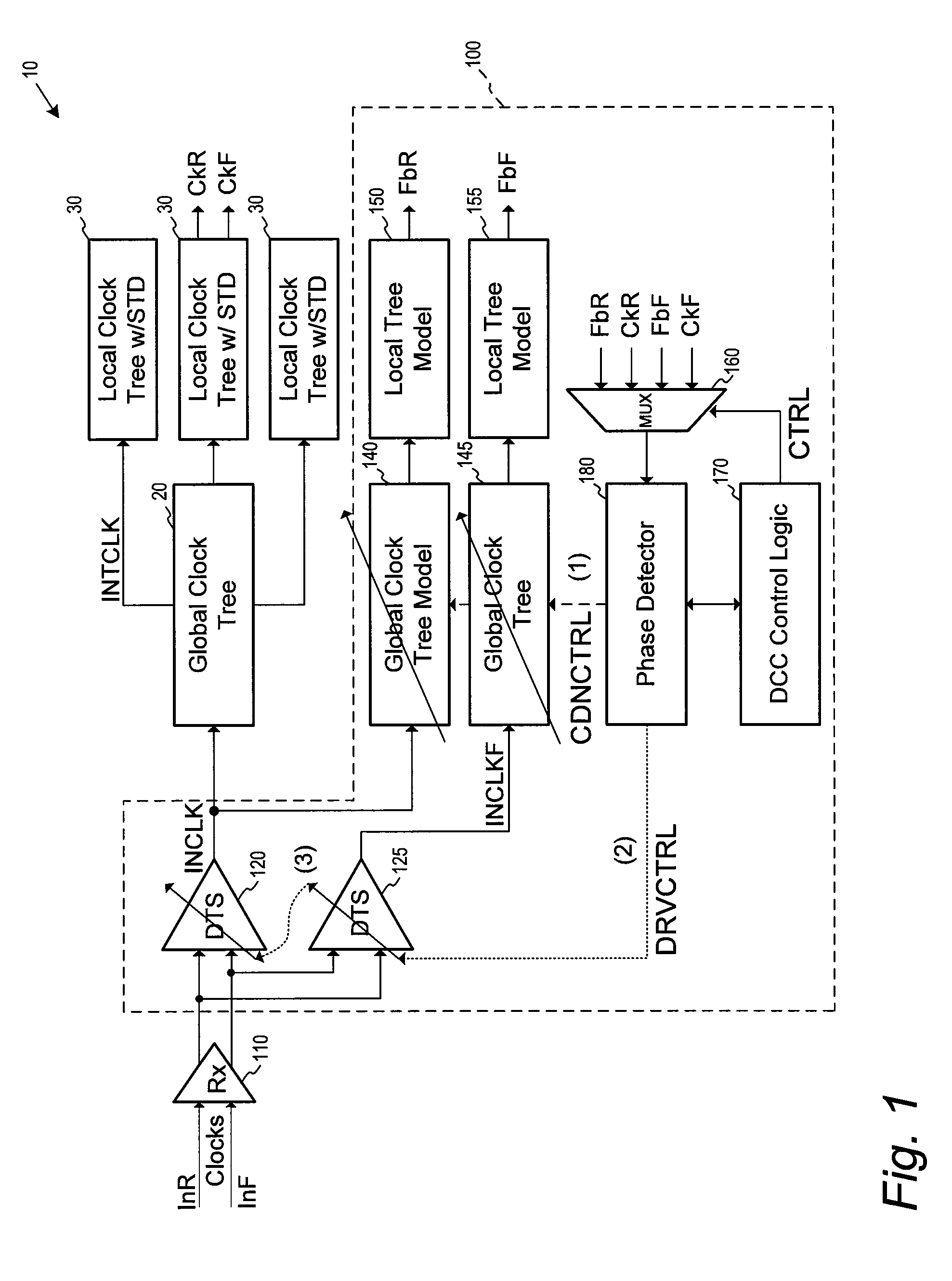
[0013]FIG. 1 illustrates a duty-cycle correction (DCC) circuit 100 according to an embodiment of the invention and a portion of clock signal distribution network (CDN) 10. The CDN 10 includes a global clock tree circuit 20 that receives an input clock signal INCLK and distributes the INCLK signal throughout the circuit. In the embodiment of FIG. 1, the INCL...


PUM


Abstract

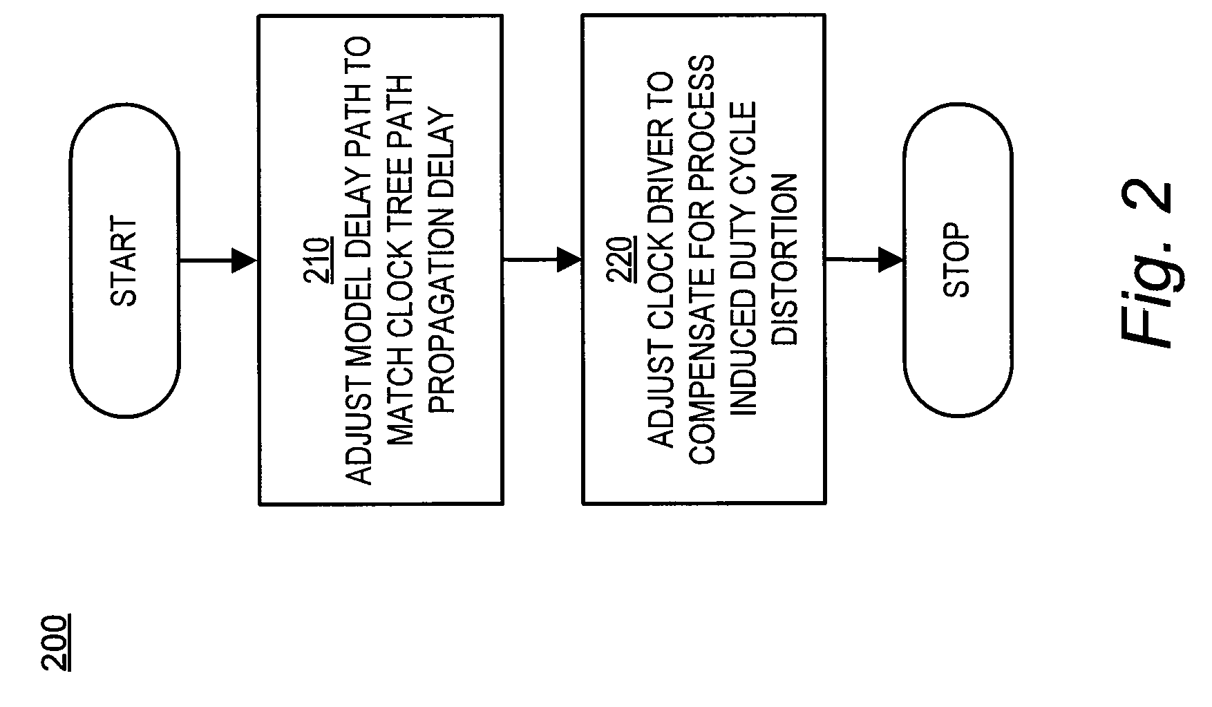
Duty-cycle correction circuits, clock distribution networks, and methods for correcting duty-cycle distortion are disclosed, including methods and apparatus for correcting duty-cycle distortion of differential output clock signals provided from a clock distribution network. In one such method, a single-ended clock signal is generated from differential input clock signals for distribution over a clock distribution network and from which the differential output clock signals are generated. A delay of a model delay path is matched to a propagation delay of the clock distribution network, and the single ended clock signal is adjusted to compensate for duty-cycle distortion.

Description

TECHNICAL FIELD[0001]Embodiments of the invention relate generally to clock signal generators, and more particularly, clock signal generators providing duty-cycle corrected clock signals over a clock distribution network.BACKGROUND OF THE INVENTION[0002]Clock signals are often used in electronic circuits for timing internal operation of various circuits necessary to execute an operation. For example, in synchronous memories, external clock signals are provided to the memory and internally distributed to different circuits of the circuit to carry out memory operations. Typically, a clock distribution network is used to route internal clock signals generated from the external clock signal to the different circuits. In this manner, operation of the integrated circuit can be coordinated with the external clock signals.[0003]When generating and routing the internal clock signals, however, maintaining the quality of the clock signals while being distributed to the various circuits can pre...

Claims


Application Information

Patent Timeline
IPC IPC(8): H03K3/017
CPCH03K5/1565H03K2005/00065H03K5/133H03L7/0814H03K2005/00071
Inventor LIN, FENG
Owner MICRON TECH INC
Learn More