
Techniques for correcting temperature measurement in magnetic resonance thermometry

a technology of magnetic resonance and temperature measurement, applied in the field of magnetic resonance imaging, can solve the problems of phase-sensitive temperature measurement invalid, erroneous temperature measurement, useless temperature measurement made using the above-mentioned phase-sensitive approach, etc., and achieve the effect of facilitating correction of temperature measuremen

Inactive Publication Date: 2011-02-24
INSIGHTEC +1
View PDF103 Cites 77 Cited by
  • Summary
  • Abstract
  • Description
  • Claims
  • Application Information

AI Technical Summary

Benefits of technology

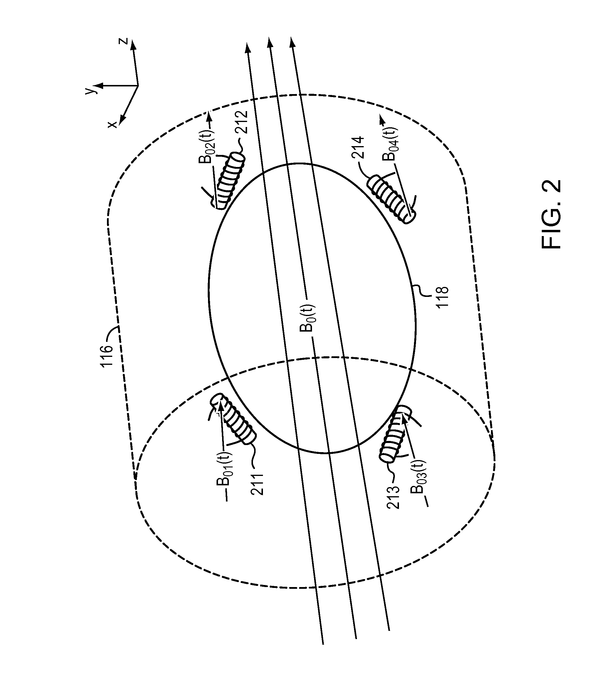
[0009]Embodiments of the present invention measure and compensate for phase shifts that arise from factors other than temperature changes, facilitating correction of temperature measurements in MR thermometry. In particular, one or more micro-coils may be placed near the region being monitored. These coils may be filled with a substance (e.g., oil) whose MR signal is temperature invariant, or may be filled with, e.g., water and placed in a region whose temperature is constant or known. The MR frequency detected by the micro-coils is unaffected by temperature, and as a result, the frequency measured at each micro-coil may be used to compute the phase background for the thermal imaging acquisition.

Problems solved by technology

Unfortunately, changes in PRF phase images do not arise uniquely from temperature changes.
Various non-temperature-related factors, such as changes in a local magnetic field due to nearby moving metal, magnetic susceptibility changes in a patient's body due to breathing or movement, and magnet or shim drifts can all lead to confounding changes in phase measurement that may render a phase-sensitive temperature measurement invalid.
The changes in magnetic field associated with magnet drift and patient motion are often severe enough to render temperature measurements made using the above-mentioned phase-sensitive approach useless.
As the elapsed time between the initial baseline phase image and the actual temperature measurement increases, concurrent (and non-temperature-related) changes in magnetic field are more likely to occur, causing erroneous temperature measurement.

Method used


Image

  • Techniques for correcting temperature measurement in magnetic resonance thermometry
  • Techniques for correcting temperature measurement in magnetic resonance thermometry
  • Techniques for correcting temperature measurement in magnetic resonance thermometry

Examples


Embodiment Construction

[0021]Embodiments of the present invention improve the utility and robustness of MR thermometry, as described below, to measure and compensate for local magnetic field changes or PRF phase shifts that arise from factors other than temperature changes.

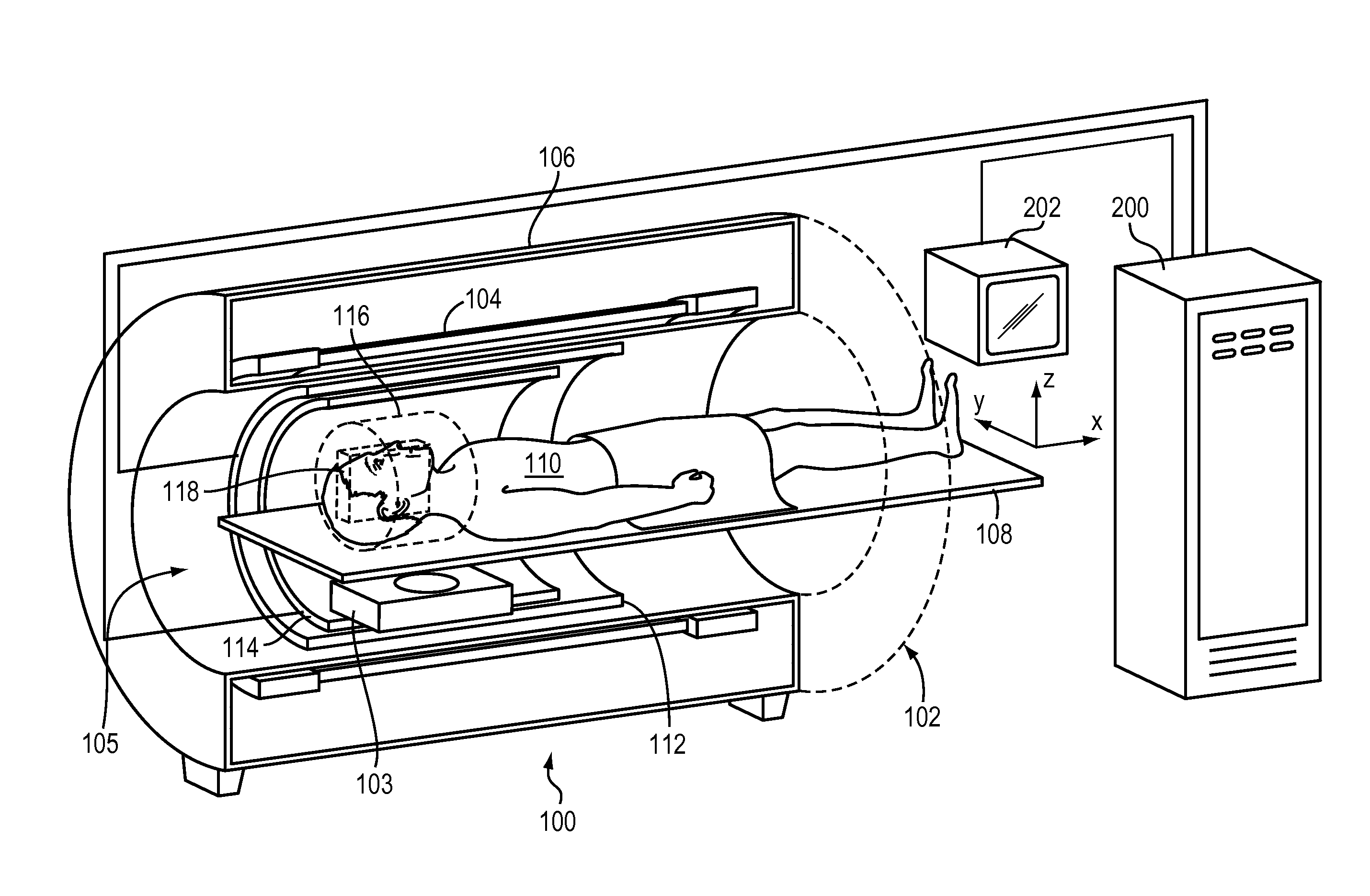
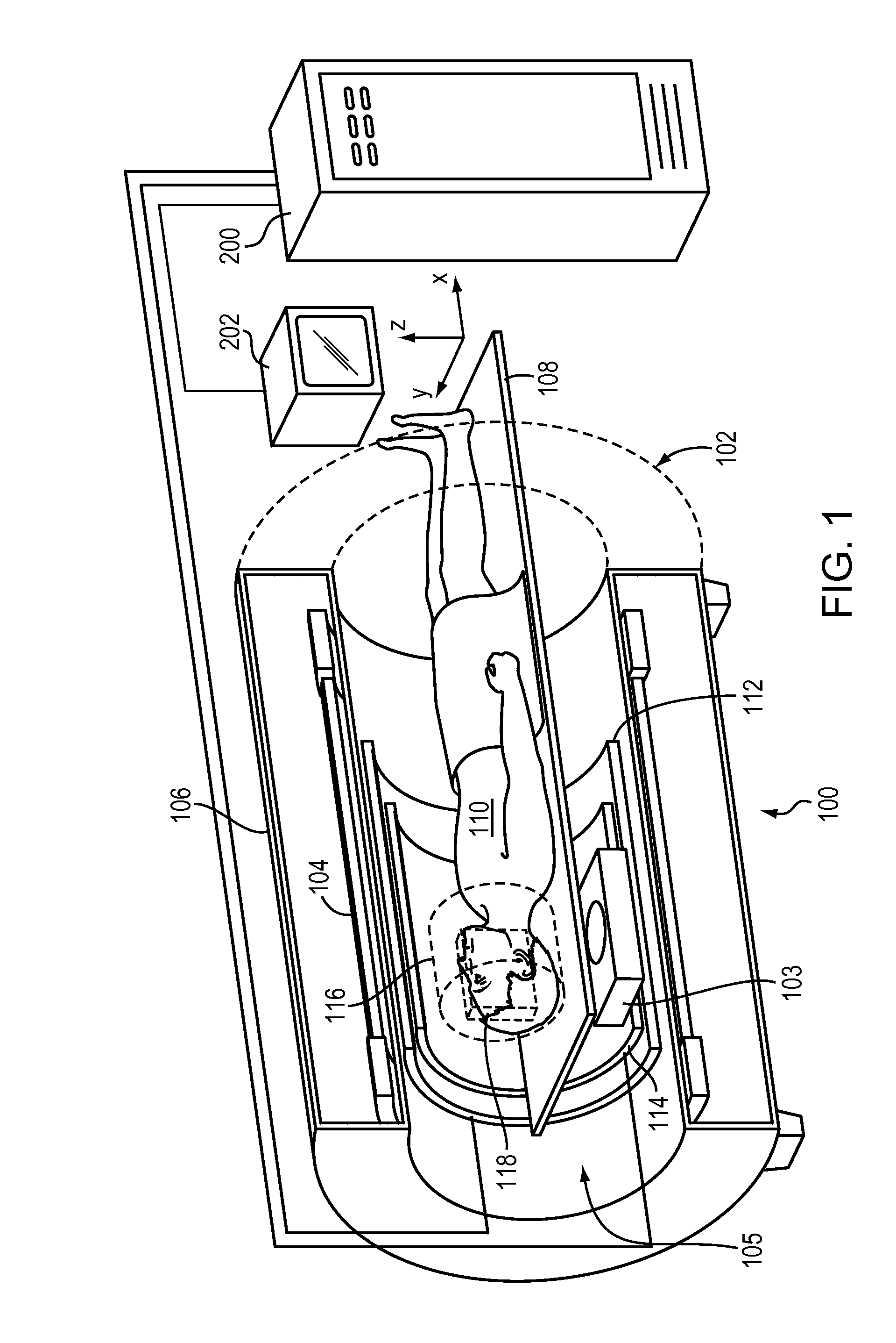
[0022]FIG. 1 shows an exemplary MRI system 100 in or for which the techniques for correcting temperature measurement in accordance with the present invention may be implemented. The illustrated MRI system 100 comprises an MRI machine 102 with a magnet bore 105. If an MR-guided procedure is being performed, a medical device 103 may be disposed within the bore of the MRI machine 102. Since the components and operation of the MRI machine are well-known in the art, only some basic components helpful in the understanding of the system 100 and its operation will be described herein.

[0023]The MRI machine 102 typically comprises a cylindrical electromagnet 104, which generates a static magnetic field within a bore 105 of the electromagnet 104. ...


PUM


Abstract

Techniques for correcting temperature measurement in MR thermometry are disclosed. In particular, phase shifts that arise from factors other than temperature changes are detected, facilitating correction of temperature measurements.

Description

FIELD OF THE INVENTION[0001]The present invention relates generally to magnetic resonance (MR) imaging, and more particularly, to techniques for correcting temperature measurement in MR thermometry.BACKGROUND OF THE INVENTION[0002]MR imaging of internal body tissues may be used for numerous medical procedures, including diagnosis and surgery. In general terms, MR imaging starts by placing a subject in a relatively uniform, static magnetic field. The static magnetic field causes hydrogen nuclei spins to align and precess about the general direction of the magnetic field. The nuclear spins align either parallel or anti-parallel to the static magnetic field. Spins in these states have slightly different energies. Furthermore, the number of spins in the lower energy (i.e., ground) state slightly exceeds the number found in the higher energy (i.e., excited) state. This slight excess in population of the lower energy state results in a net magnetization. Radio frequency (RF) magnetic fiel...

Claims


Application Information

Patent Timeline
IPC IPC(8): A61B5/055
CPCG01R33/24G01R33/243G01R33/4804G01R33/58G01R33/565G01R33/56509G01R33/56563G01R33/4814
Inventor ASSIF, BENNYDUMOULIN, CHARLES L.MALLOZZI, RICHARD P.DARROW, ROBERT D.
Owner INSIGHTEC
Learn More