Cooling system of ring segment and gas turbine
- Summary
- Abstract
- Description
- Claims
- Application Information
AI Technical Summary
Benefits of technology
Problems solved by technology
Method used
Image
Examples
first embodiment
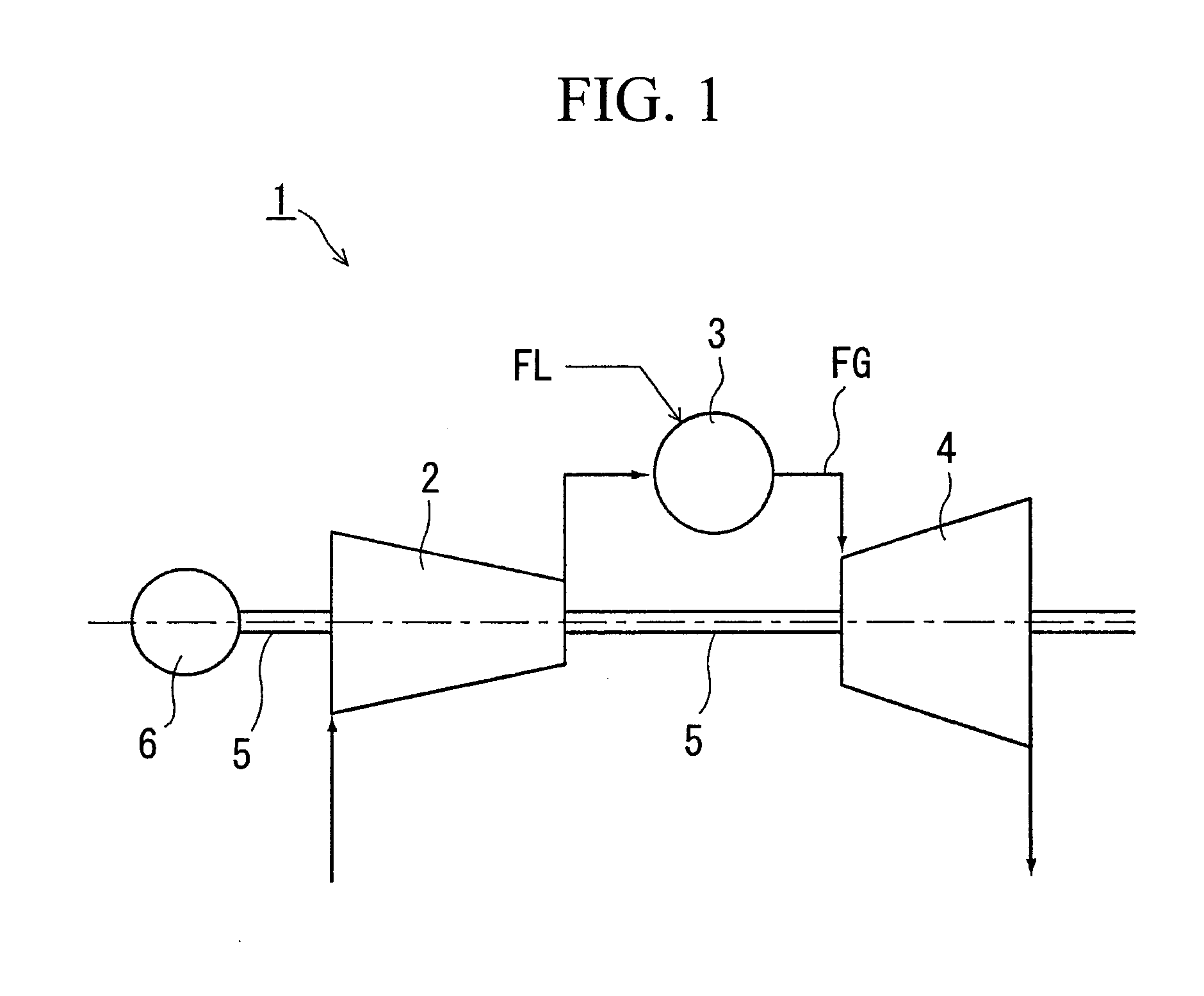
A description of the first embodiment shall be given based on FIGS. 1 to 7 and FIG. 11.
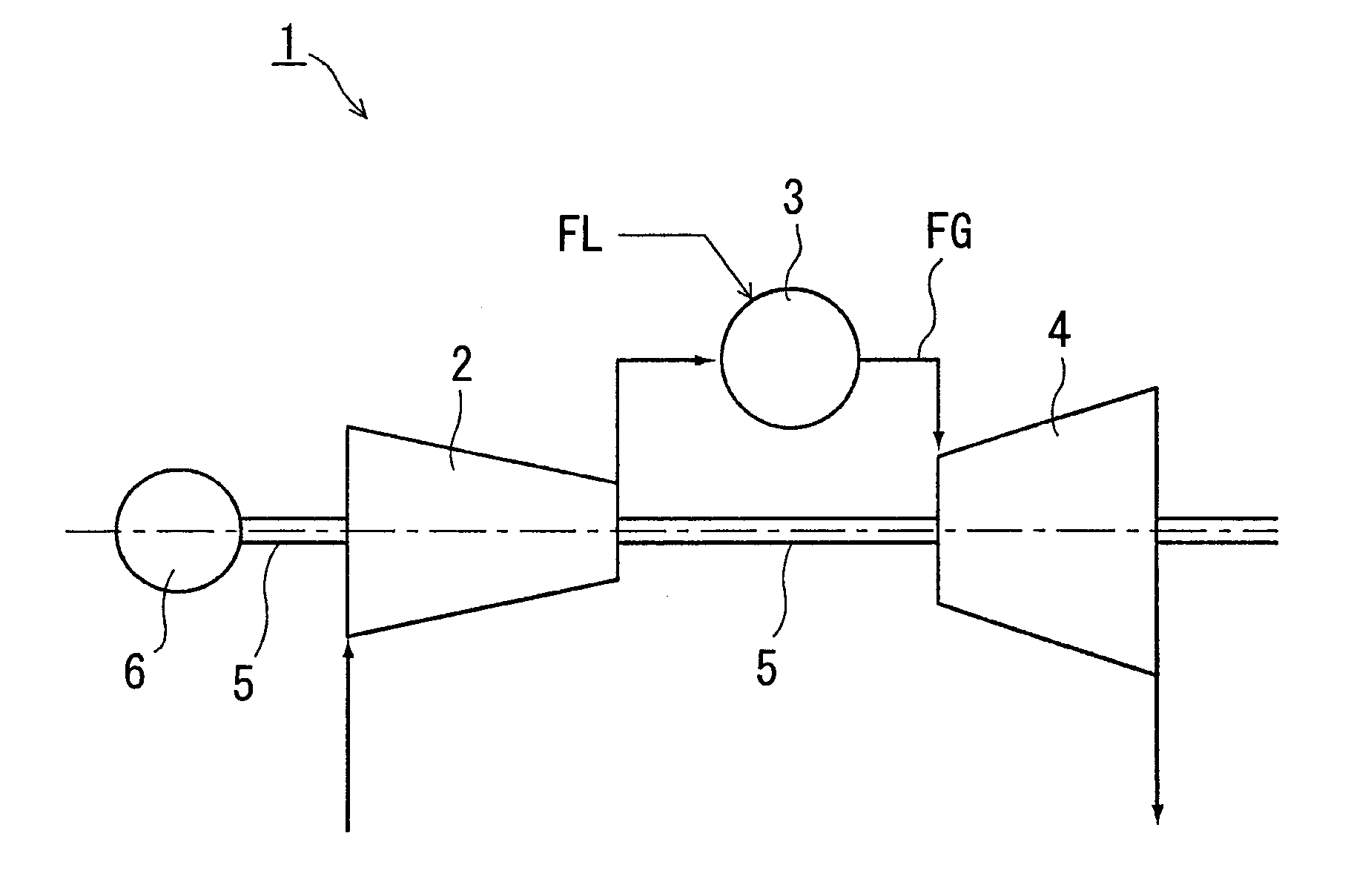
FIG. 1 is an overall configuration diagram of the gas turbine. A gas turbine 1 has as main constituent elements a compressor 2 that compresses combustion air, a combustor 3 that injects fuel FL into the combustion air that is sent from the compressor 2, causes a combustion, and generates combustion gas, a turbine 4 that is positioned on the downstream of this combustor 3 and driven by the combustion gas that has left the combustor 3, a generator 6, and a rotating shaft 5 that integrally couples the compressor 2, the turbine 4, and the generator 6.
Since the turbine 4 has the same constitution as the content described in FIG. 11 of the background art, a detailed description thereof shall be omitted. The same names and reference numerals shall be used for common component names and reference numerals.
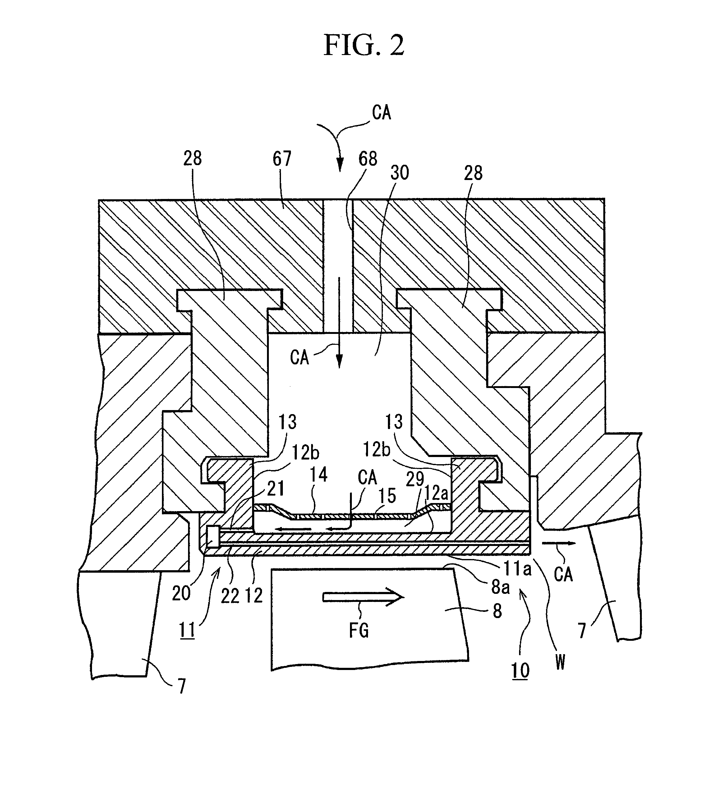
FIG. 2 shows a cross section of the essential portions of the ring segment of the gas turbine.
A ring ...
first modification
[First Modification]
FIG. 8 shows an arrangement example that differs from the first embodiment, in relation to the first cooling passage and the second cooling passage. The first modification, compared to the first embodiment, is the same on the point of arranging cooling passages in an annular shape at the same hole pitch with respect to the rotation direction R of the rotating shaft 5, but differs on the point of the second cooling passage 22 having a smaller hole diameter than the first cooling passage 21. Also, it differs on the point of the hole pitch of the second cooling passage 22 in the rotation direction R of the rotating shaft 5 being greater than the hole pitch of the second cooling passage 22 in the rotation direction R. If these hole diameters and hole pitches of the first cooling passage 21 and the second cooling passage 22 are adopted, a sufficient amount of the cooling air that is supplied to the second cooling passage is secured for cooling, and compared to the fir...
second embodiment
FIG. 9 shows a partial cross-section of the upstream end portion of the segment body of the second embodiment.
Compared to the first embodiment, the present embodiment differs on the point of the first cooling passage having a slope in the axial direction of the rotating shaft with respect to the second cooling passage, and in other aspects is the same as the first embodiment. Note that the component elements that are in common with the first embodiment use the same component names and reference numbers as the first embodiment, and detailed descriptions thereof shall be omitted.
In FIG. 9, it is the same as the first embodiment on the point of a second cooling passage 45 being arranged in the axial direction of the rotating shaft 5 along the inner circumferential surface 11a of the segment body 11 until the downstream end face 17a, and being arranged in an annular shape at the same hole pitch in the rotation direction R of the rotating shaft. However, it differs on the point of a firs...
PUM
 Abstract
Description
Claims
Application Information
 - R&D
- Intellectual Property
- Life Sciences
- Materials
- Tech Scout
- Unparalleled Data Quality
- Higher Quality Content
- 60% Fewer Hallucinations
Browse by: Latest US Patents, China's latest patents, Technical Efficacy Thesaurus, Application Domain, Technology Topic, Popular Technical Reports.
© 2025 PatSnap. All rights reserved.Legal|Privacy policy|Modern Slavery Act Transparency Statement|Sitemap|About US| Contact US: help@patsnap.com


