
Shift device

Inactive Publication Date: 2011-02-17
HONDA MOTOR CO LTD
View PDF13 Cites 10 Cited by
  • Summary
  • Abstract
  • Description
  • Claims
  • Application Information

AI Technical Summary

Benefits of technology

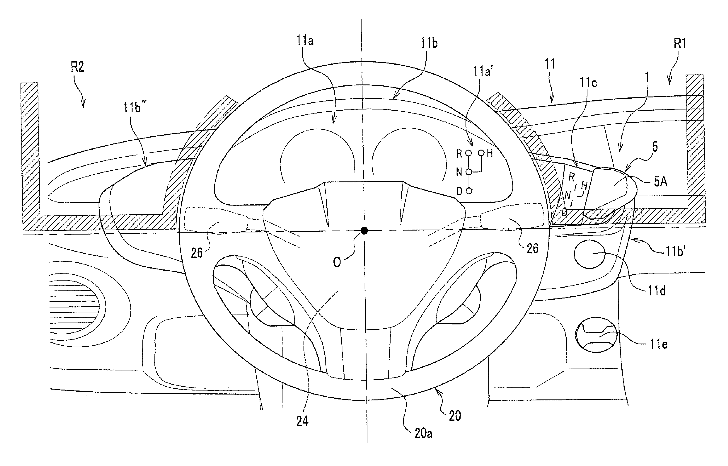
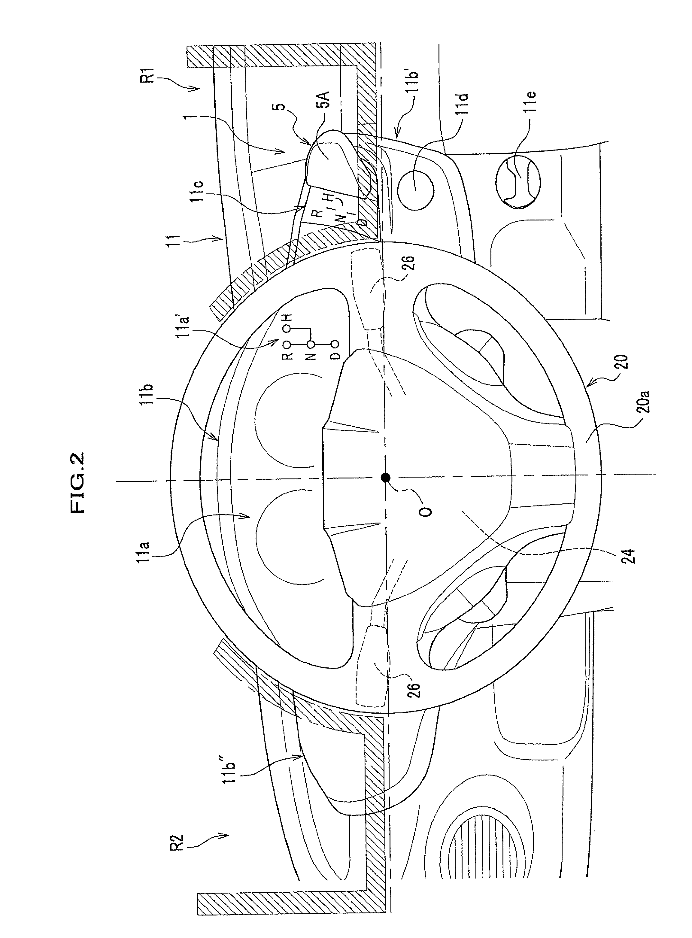
[0010]In accordance with the shift device, the shift lever is not hidden by the steering wheel from the viewpoint of the driver. Further, since the shift lever is arranged in the area of the instrumental panel upper than the center axis of the steering wheel which is likely to be seen in the peripheral vision of the driver M, the position of the shift lever can be easily recognized, providing an excellent visibility. As the shift lever is arranged in the area of the instrumental panel and protrudes toward the side of the driver, the operation of the shift lever is not obstructed by other operation switches (a blinker switch or a washer switch) which are provided to a steering column. Thus, the operability of the shift lever is enhanced.
[0011]As the shift lever is arranged above the center axis of the steering wheel, the shift lever can be arranged in the vicinity of the steering wheel, which further enhances the operability of the shift lever. If the shift lever is not arranged in the area upper than the center axis of the steering wheel but is arranged to the side of the center shaft of the steering wheel, the shift lever is positioned away from the steering wheel, which deteriorates the operability of the shift lever. If the shift device is arranged lower than the center axis of the steering wheel, the shift device needs to be arranged in a position other than the driving sheet, which makes the shift lever away from the steering wheel, deteriorating the operability of the shift lever.
[0012]In contrast, in the present invention, as the shift lever is arranged in an area upper than the center shaft of the steering wheel, the shift lever is positioned in the vicinity of the steering wheel, which enhances the operability of the shift lever.
[0014]In the shift device, when the air bag system is operated and the air bag is expanded due to an impact applied by a collision, the air bag is expanded between the shift lever and the driver. Thus, the expanded air bag between the shift lever and the driver eliminates the risk that the shift lever comes in contact with the driver, which advantageously eliminates the need to provide a shock absorbing mechanism to the shift lever. In short, even if the shift lever protrudes toward the side of the driver, there is no need to provide a shock absorbing mechanism to the shift device, which makes the configuration of the shift device be simpler and reduces the manufacturing cost thereof.
[0016]In accordance with the shift device, as the shift lever is arranged on the meter visor in the instrumental panel, the driver's visual line can be smoothly moved from the display portion to the shift lever, providing an excellent visibility. It is also possible to operate the shift lever easily just by extending the hand gripping the steering wheel toward the instrumental panel in front of the steering wheel. Thus, the shift device can be realized of which operability is further enhanced. The shift device also realizes a natural operation feeling and allows a smooth shift operation since the shift lever can be operated just by extending the hand gripping the steering wheel to the instrumental panel in front of the steering wheel. It is also possible to readily recognize the position of the shift lever without visually checking the position of the shift lever during driving, which allows the driver to operate the shift lever easily while ensuring the front visual field.
[0017]In accordance with the present invention, the shift device of which visibility and operability are excellent can be provided.

Problems solved by technology

However, the shift devices disclosed in Japanese Patent No. 2933965 and Japanese Unexamined Patent Application Publication No. 05-246260 have a problem that it is difficult for a driver to see a shift lever since the shift lever is hidden by the steering wheel.
These shift devices also have a problem that their operability is not good since the shift lever is arranged in the operating range of a wiper control lever from the viewpoint of the driver.
The shift device disclosed in Japanese Unexamined Patent Application Publication No. 05-246260 also has a problem that its operability is deteriorated because the shift device is provided on the same height level as the steering wheel shaft or below the height level of the steering wheel shaft (similarly to a general shift device arranged on an instrumental panel) and the shift device is arranged away from the steering wheel.
If the shift lever is not arranged in the area upper than the center axis of the steering wheel but is arranged to the side of the center shaft of the steering wheel, the shift lever is positioned away from the steering wheel, which deteriorates the operability of the shift lever.
If the shift device is arranged lower than the center axis of the steering wheel, the shift device needs to be arranged in a position other than the driving sheet, which makes the shift lever away from the steering wheel, deteriorating the operability of the shift lever.

Method used


Image

  • Shift device
  • Shift device
  • Shift device

Examples


Embodiment Construction

[0051]An embodiment of the present invention is described with reference to the accompanying drawings.

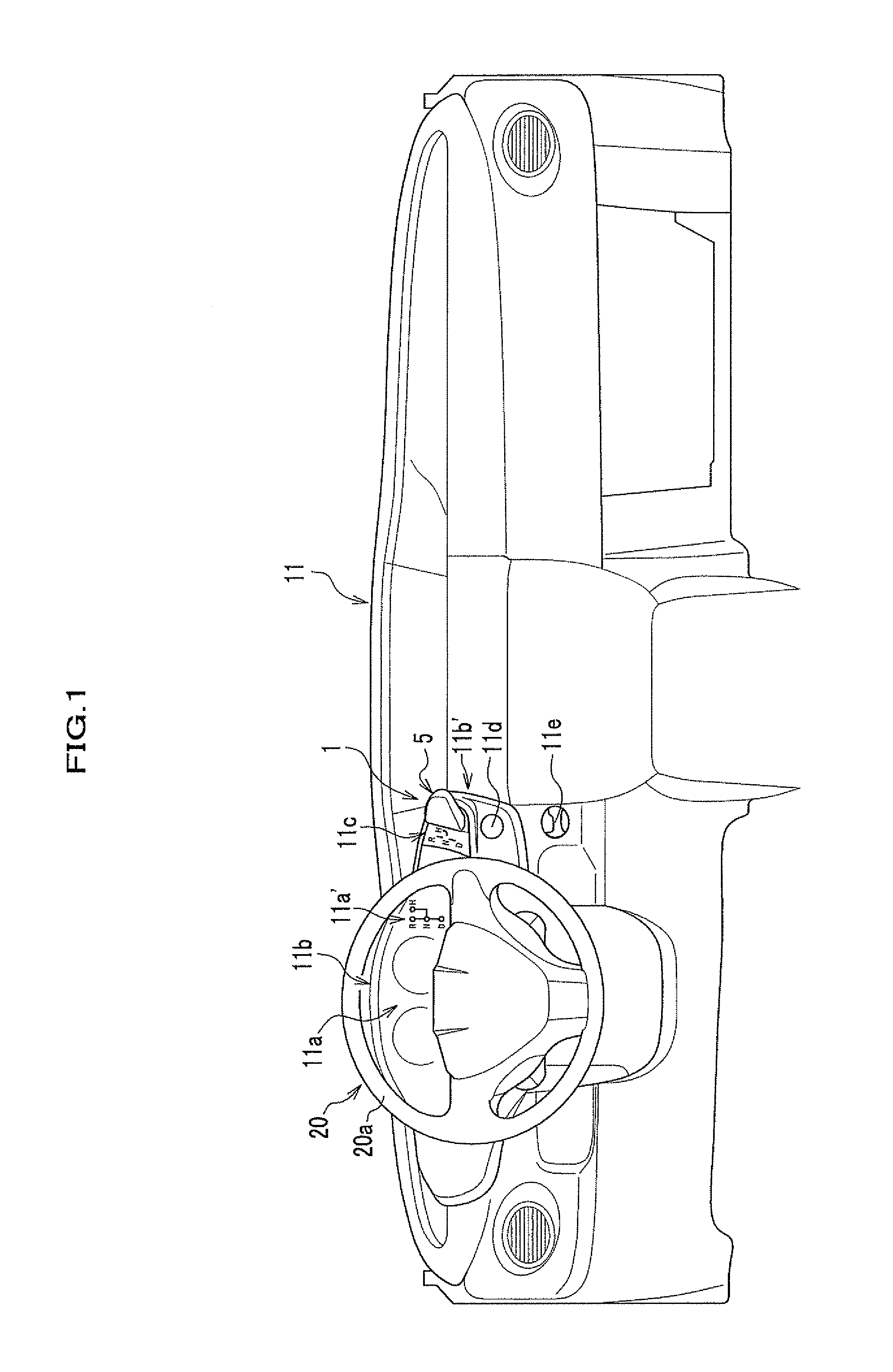
[0052]FIG. 1 is a view showing substantially entire configuration of an instrumental panel on which a shift device of the embodiment of the present invention is arranged. FIG. 2 is a view showing a position on which the shift device is arranged. FIG. 3 is a perspective view showing a mounting state of the shift device on a steering hanger beam. Hereinafter, directions of “front-back”, “right-left”, and “up-down” in this specification are the same as those of the shift device which is mounted on a vehicle body. Incidentally, a shift device 1 mounted on a vehicle body of an automobile is described hereinafter, however, the type of a vehicle with which the shift device 1 is provided is not limited to an automobile.

[0053]As shown in FIG. 1, the shift device 1 is arranged on a right end portion 11b′ of a meter visor 11b of an instrumental panel 11 which is provided in front of front shee...


PUM


Abstract

There is provided a shift device of which visibility and operability is excellent. The shift device 1 includes a shift lever 5 which operates a gear position of a transmission. The shift lever is arranged in an area R1 of an instrumental panel 11 which is outside of a steering wheel 20 and upper than the center axis O of the steering wheel 20 from the viewpoint of the driver and protruding toward the driver. A center part of the steering wheel 20 is provided with an air bag system, and the shift lever 5 is arranged in an expansion area of an air bag of the air bag system from the viewpoint of the driver.

Description

BACKGROUND OF THE INVENTION[0001]1. Field of the Invention[0002]The present invention relates to a shift device for switching a running range of an automatic transmission provided in a vehicle such as an automobile.[0003]2. Description of the Related Art[0004]Conventionally, a shift device is generally arranged on a center console which is provided between the right and left front sheets, however, there has been recently proposed a shift device which is arranged in the vicinity of a steering wheel for enlarging a space in a vehicle cabin to enhance its layout capability.[0005]For example, Japanese Patent No. 2933965 discloses a shift device which is provided on a side of a steering column. Japanese Unexamined Patent Application Publication No. 05-246260 discloses a shift device provided in a part of an instrumental panel.[0006]However, the shift devices disclosed in Japanese Patent No. 2933965 and Japanese Unexamined Patent Application Publication No. 05-246260 have a problem that i...

Claims


Application Information

Patent Timeline
IPC IPC(8): B60K20/06
CPCB60K20/06F16H59/0204Y10T74/2014Y10T74/20146F16H59/0278
Inventor ISHIHARA, YOKOKOMATSU, ATSUSHINISHIKAWA, YOSHIKAZUOKUHARA, TATSUYANAKAMURA, TAKAHIRO
Owner HONDA MOTOR CO LTD
Learn More