
Building Insulation Sheathing Systems and Methods of Use Thereof

Inactive Publication Date: 2011-02-17
SUPREME ENERGY PRODS
View PDF9 Cites 15 Cited by
  • Summary
  • Abstract
  • Description
  • Claims
  • Application Information

AI Technical Summary

Benefits of technology

[0033]Embodiments of the present invention relate to a building insulation sheathing system that provides for efficient installation of insulation, material and labor reduction during installation, as well as provides a stable structure for ease in attachment of protective and / or decorative cladding to a building. The present invention further includes a method for insulating a building using the sheathing system of the present invention.

Problems solved by technology

Unfortunately, insulation systems in the market today have a number of shortfalls including, but not limited to, energy inefficiency, complicated installation processes, increased dew point within exterior walls thereby supporting the growth of mold, noncontiguous insulation thereby providing outlets for heat and cooling loss, and design deficiencies that inhibit incorporation into existing structures.
Unfortunately, there are many disadvantages in using such systems.
Unfortunately, fiberglass insulation has some disadvantages including the following:It performs way below its marketed R-Values.Has problems with mold and mildew.It does not stop any thermo-bridging.
(rims)Requires a vapor barrier.Requires a weather barrier.Its cavity filled insulation.Does not control the convection looping process.The dew point is in your stud cavity.The stud space can not be used for mechanical without affecting the performance of the wall.
However, spray foam has a number of disadvantages including the following:The cost is about 3.5 times higher than fiberglass.It does not control thermo-bridging.
ICFs have a number of disadvantages including the following:Costs are high.It is not yet considered a conventional build.Mold problems.
The construction industry and home improvement product manufacturers still have found difficulties in remedying the problems identified above in a single system.

Method used


Image

  • Building Insulation Sheathing Systems and Methods of Use Thereof
  • Building Insulation Sheathing Systems and Methods of Use Thereof
  • Building Insulation Sheathing Systems and Methods of Use Thereof

Examples


Embodiment Construction

[0056]The embodiments of the present invention described below are not intended to be exhaustive or to limit the invention to the precise forms disclosed in the following detailed description. Rather, the embodiments are chosen and described so that others skilled in the art can appreciate and understand the principles and practices of the present invention.

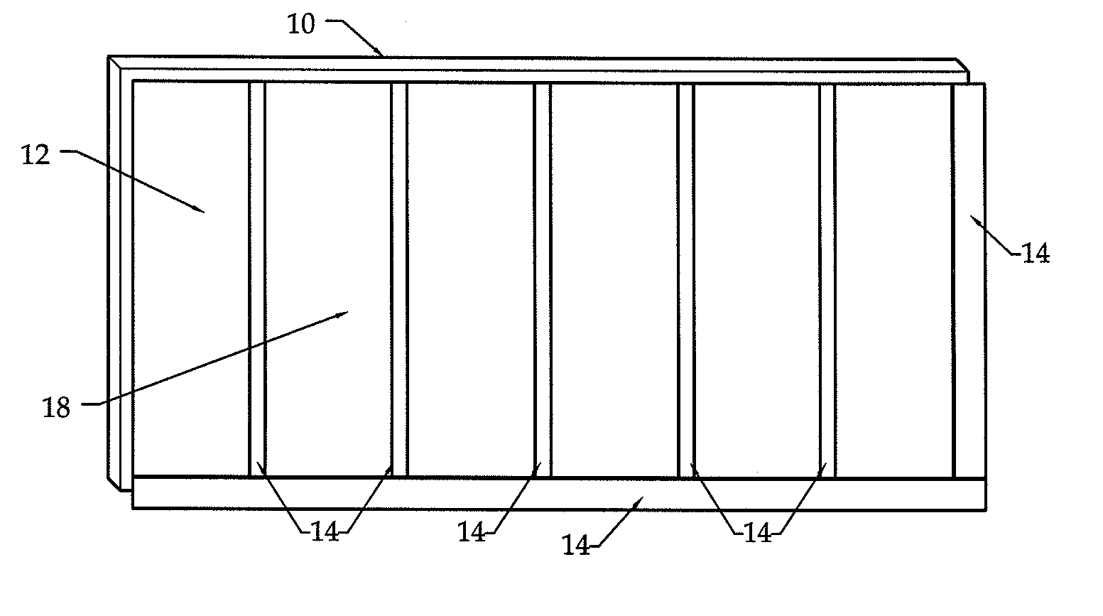
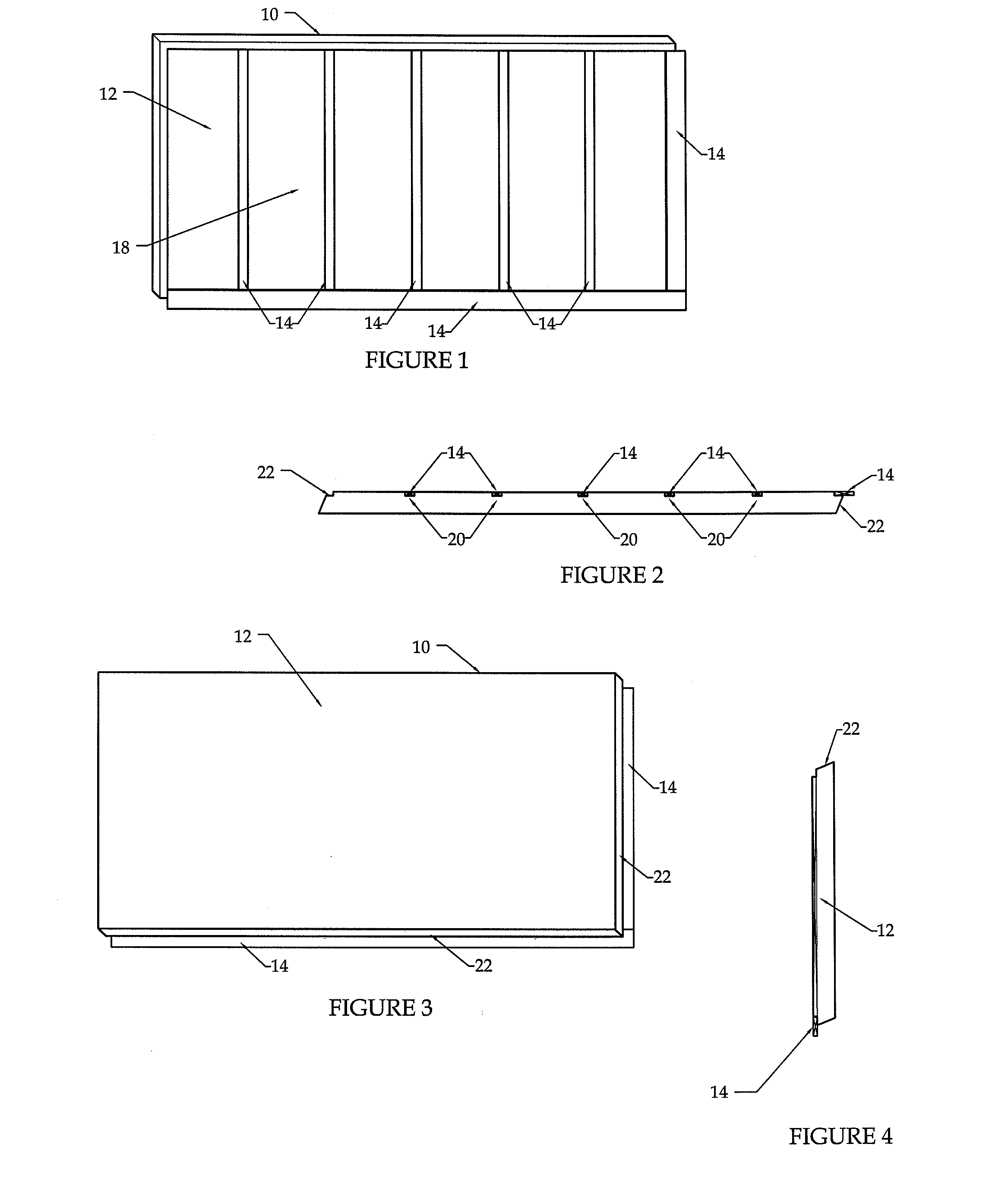
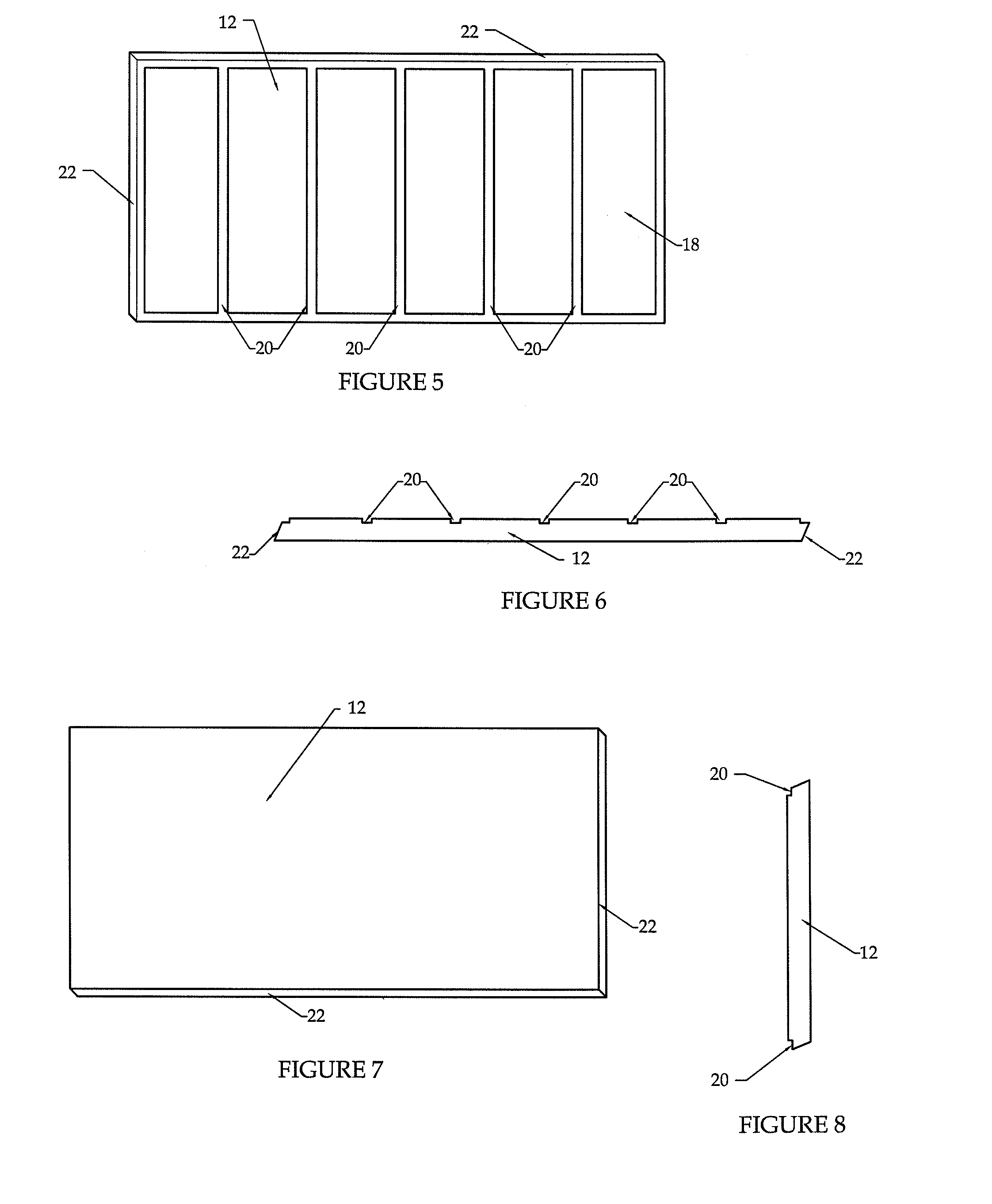
[0057]FIGS. 1-21 depict various embodiments of the building insulation sheathing system of the present invention. In general the insulation sheathing system 10 of the present invention includes one or more insulation panels 12, one or more securing battens 14, and one or more fastening devices 16 to secure the panels 12 and battens 14 to the outer surface of the frame and / or studs of a building structure.

[0058]The insulation panels used in the sheathing system of the present invention are normally made from an insulating material and are shaped so that they are easily adjoined to the frame and / or studs of a building and can be at...


PUM


Abstract

The present invention relates to a building insulation sheathing system that provides for efficient installation of insulation, material and labor reduction during installation, as well as provides a stable structure for ease in attachment of protective and / or decorative cladding to a building. The present invention further includes a method for insulating a building using the sheathing system of the present invention.

Description

CROSS-REFERENCE TO RELATED APPLICATION[0001]This application claims priority to U.S. Provisional Application Ser. No. 61 / 274,202, filed on Aug. 13, 2009. The contents of the previously mentioned provisional application is incorporated by reference herein.FIELD OF THE INVENTION[0002]The present invention relates to a building insulation sheathing system that provides for efficient installation of insulation, material and labor reduction during installation, as well as provides a stable structure for ease in attachment of protective and / or decorative cladding to a building. The present invention further includes a method for insulating a building using the sheathing system of the present invention.BACKGROUND OF THE INVENTION[0003]The insulation of buildings, whether residential or commercial, is an incredibly important part of the structure and when installed properly, ensures energy and financial efficiency for the life of the building. Unfortunately, insulation systems in the market...

Claims


Application Information

Patent Timeline
IPC IPC(8): E04C2/10E04B1/62E04B2/00
CPCE04B1/26E04B1/80E04F13/0803E04B2001/268E04B2001/386E04B2/707
Inventor HEGLAND, ADAM JOEL
Owner SUPREME ENERGY PRODS
Learn More