
1:N sparing of router resources at geographically dispersed locations

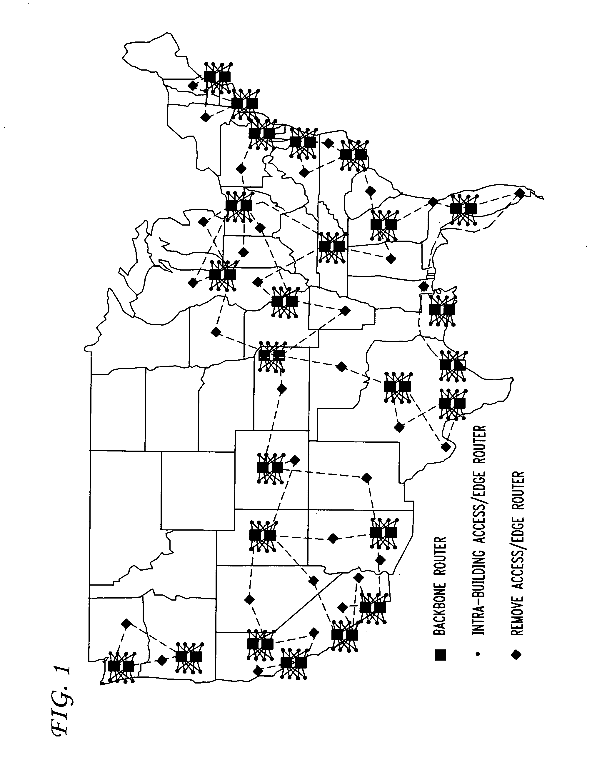
a router and geographically dispersed technology, applied in the field of network engineering, can solve the problems of operator traffic throughput, the number of ports required on the br may exceed equipment capabilities, etc., and achieve the effect of reducing the quantity of br ports

Active Publication Date: 2011-02-10
AT&T INTPROP I L P
View PDF3 Cites 15 Cited by
  • Summary
  • Abstract
  • Description
  • Claims
  • Application Information

AI Technical Summary

Benefits of technology

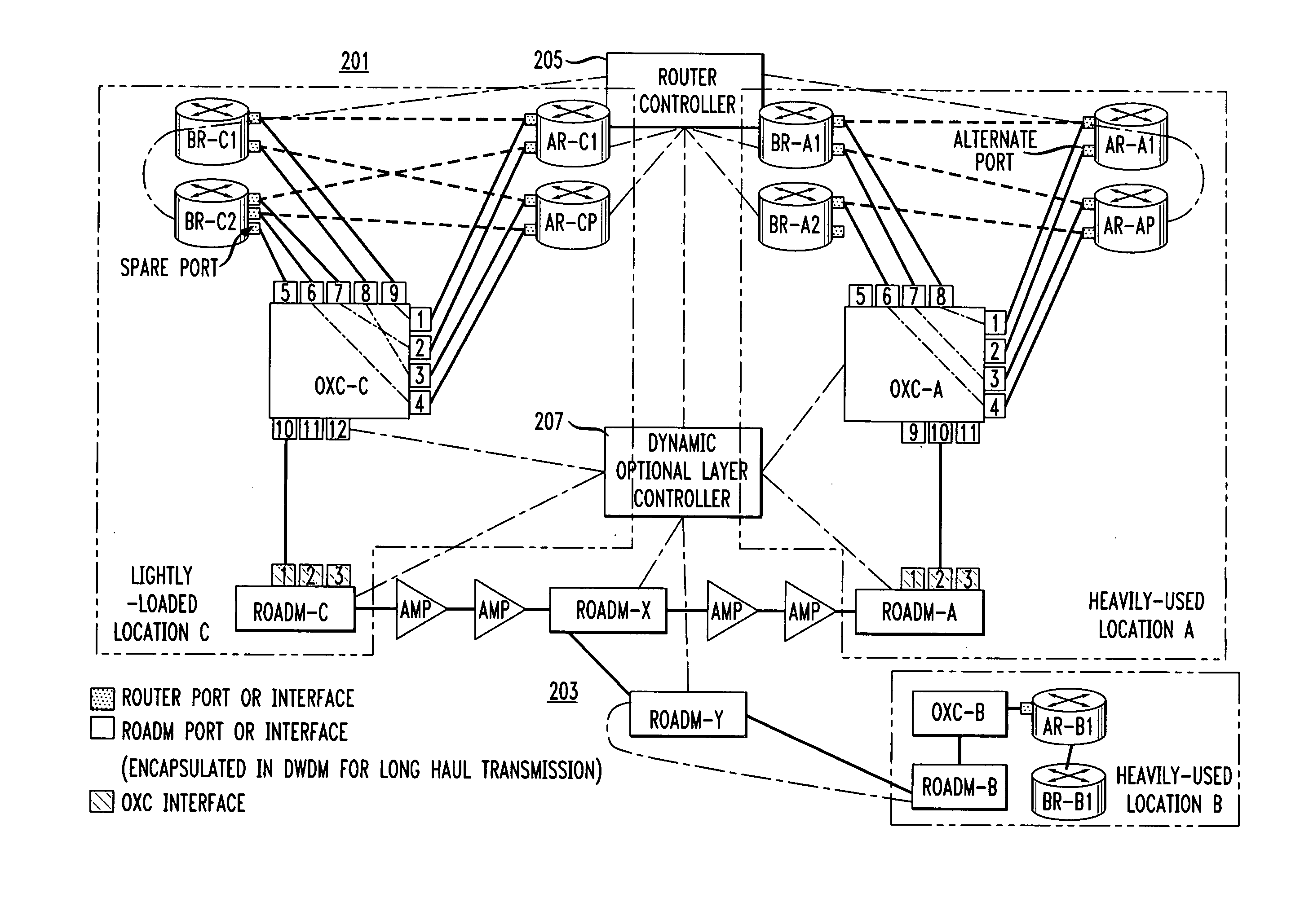
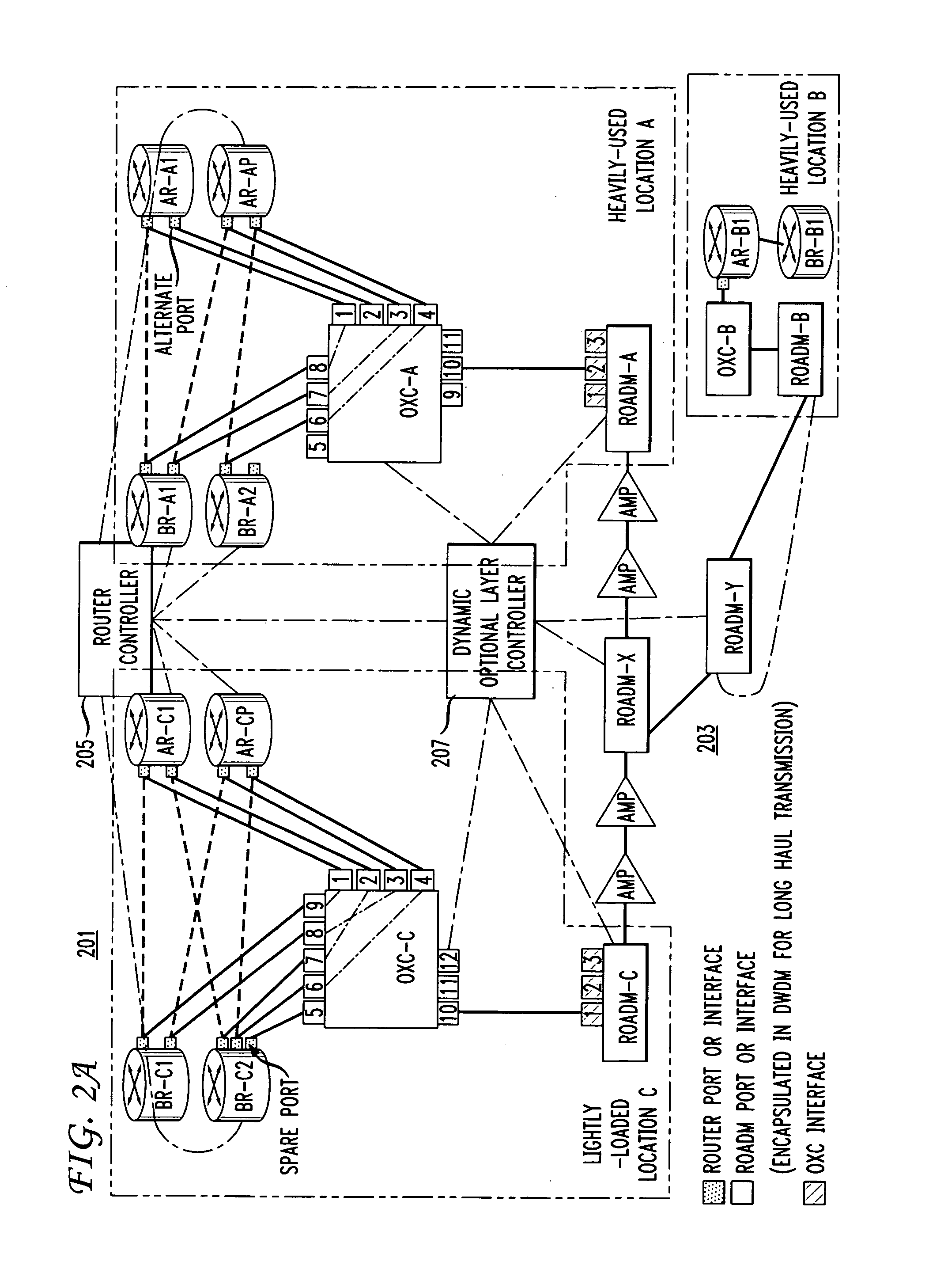
[0012]The inventors have discovered that it would be desirable to have systems and methods that dynamically configure high-speed data link lightpaths between ARs and BRs at geographically dispersed locations. Embodiments reduce the quantity of BR ports used in dual BR-homed networks.
[0013]Embodiments improve network reliability by implementing a network architecture that connects alternate ports from ARs at a heavily-used location to spare ports of BRs at lightly-used locations over an optical network.
[0014]One or more configurable data link lightpaths between alternate AR and spare BR ports in different locations may be rapidly and dynamically configured to create inter-office AR-BR link lightpaths from ARs in heavily-used locations to BRs in lightly-used locations. The architecture conserves cost by achieving a 1:N restoration effect, where BRs in one lightly-used location can restore AR-BR links from one or more heavily-used locations, as long as AR-BR intra-office link failures experienced at the different heavily-used locations are not simultaneous. Spare wavelengths and facilities in the optical network may be shared over common routes for link failures as long as the failure of any BR equipment (such as a router port) or intra-office facilities (such as fiber connecting the router ports) in any CO is not simultaneous with a failure of BR equipment or facilities in any other CO and not simultaneous with a failure of needed optical network equipment (such as a port on a Reconfigurable Optical Add Drop Multiplexers (ROADM)) or inter-office facilities (such as inter-office fiber).
[0018]Another aspect of the invention is a network architecture that includes one or more Backbone Routers (BRs) having a client-side spare port and one or more Access Routers (ARs) having a network-side alternate port that provides network reliability by connecting an AR alternate port with a BR spare port over an optical network comprising a configurable data link lightpath comprising a first Optical cross-Connect (OXC) connected to a network-side AR alternate port and a first Reconfigurable Optical Add Drop Multiplexer (ROADM), the first ROADM connected to the optical network, and a second OXC connected to a client-side BR spare port and a second ROADM, the second ROADM connected to the optical network, a router controller connected to each BR and AR, a dynamic optical layer controller connected to each OXC, ROADM and the optical network, and the router controller configured to provide data link control between ARs that have network-side alternate ports and BRs that have client-side spare ports and the dynamic optical layer controller configured to determine a data link lightpath between AR alternate ports connected OXCs and BR spare ports connected OXCs.

Problems solved by technology

There are two disadvantages to the standard architecture:1) at a location having a large number of ARs, the required numbers of ports on a BR may exceed equipment capabilities, and2) all of the links between an AR and its first BR need to have sufficient capacity to support all traffic from the same AR and its second BR if the second BR fails and vice-versa.
The challenge for network operators is to maintain traffic throughput under the most probable failure conditions.

Method used


Image

  • 1:N sparing of router resources at geographically dispersed locations
  • 1:N sparing of router resources at geographically dispersed locations
  • 1:N sparing of router resources at geographically dispersed locations

Examples


Embodiment Construction

[0026]Embodiments of the invention will be described with reference to the accompanying drawing figures wherein like numbers represent like elements throughout. Before embodiments of the invention are explained in detail, it is to be understood that the invention is not limited in its application to the details of the examples set forth in the following description or illustrated in the figures. The invention is capable of other embodiments and of being practiced or carried out in a variety of applications and in various ways. Also, it is to be understood that the phraseology and terminology used herein is for the purpose of description and should not be regarded as limiting. The use of “including,”“comprising,” or “having,” and variations thereof herein is meant to encompass the items listed thereafter and equivalents thereof as well as additional items.

[0027]The terms “connected” and “coupled” are used broadly and encompass both direct and indirect connecting, and coupling. Furthe...


PUM


Abstract

Systems and methods are described that that dynamically configure high-speed data link lightpaths between access routers and backbone routers at geographically dispersed locations to reassign traffic when a backbone router fails or is removed from service. Embodiments reduce the quantity of backbone router ports used in dual backbone router-homed networks.

Description

BACKGROUND OF THE INVENTION[0001]The invention relates generally to network engineering. More specifically, the invention relates to systems and methods that configure high-speed data links between dispersed locations to reroute data traffic between Backbone Routers (BRs).[0002]BRs are routers designed to operate in the Internet backbone or core. A BR supports multiple telecommunications interfaces of the highest speed in use in the core Internet and forwards Internet Protocol (IP) packets at full speed over all of them. BRs also support the routing protocols being used in the core.[0003]A BR is distinct from a Provider Edge (PE) router, also known as an Access Router (AR), since ARs are located at the edge of a backbone network and connect to BRs. ARs contain interfaces that connect to multiple customers and provide a diverse set of IP services such as Virtual Private Networks (VPNs), multicast, and other protocols implemented in customer private network domains and Local Area Netw...

Claims


Application Information

Patent Timeline
IPC IPC(8): H04J14/02H04L12/28
CPCH04J14/0291H04Q11/0062H04B10/27H04Q2011/0081H04Q11/0071
Inventor DOVERSPIKE, ROBERT DUNCANSINHA, RAKESH KUMARMAGILL, PETER D.YATES, JENNIFER
Owner AT&T INTPROP I L P
Learn More