
Pulsed laser triggered high speed microfluidic switch and applications in fluorescent activated cell sorting

Active Publication Date: 2011-02-10
RGT UNIV OF CALIFORNIA
View PDF26 Cites 133 Cited by
  • Summary
  • Abstract
  • Description
  • Claims
  • Application Information

AI Technical Summary

Benefits of technology

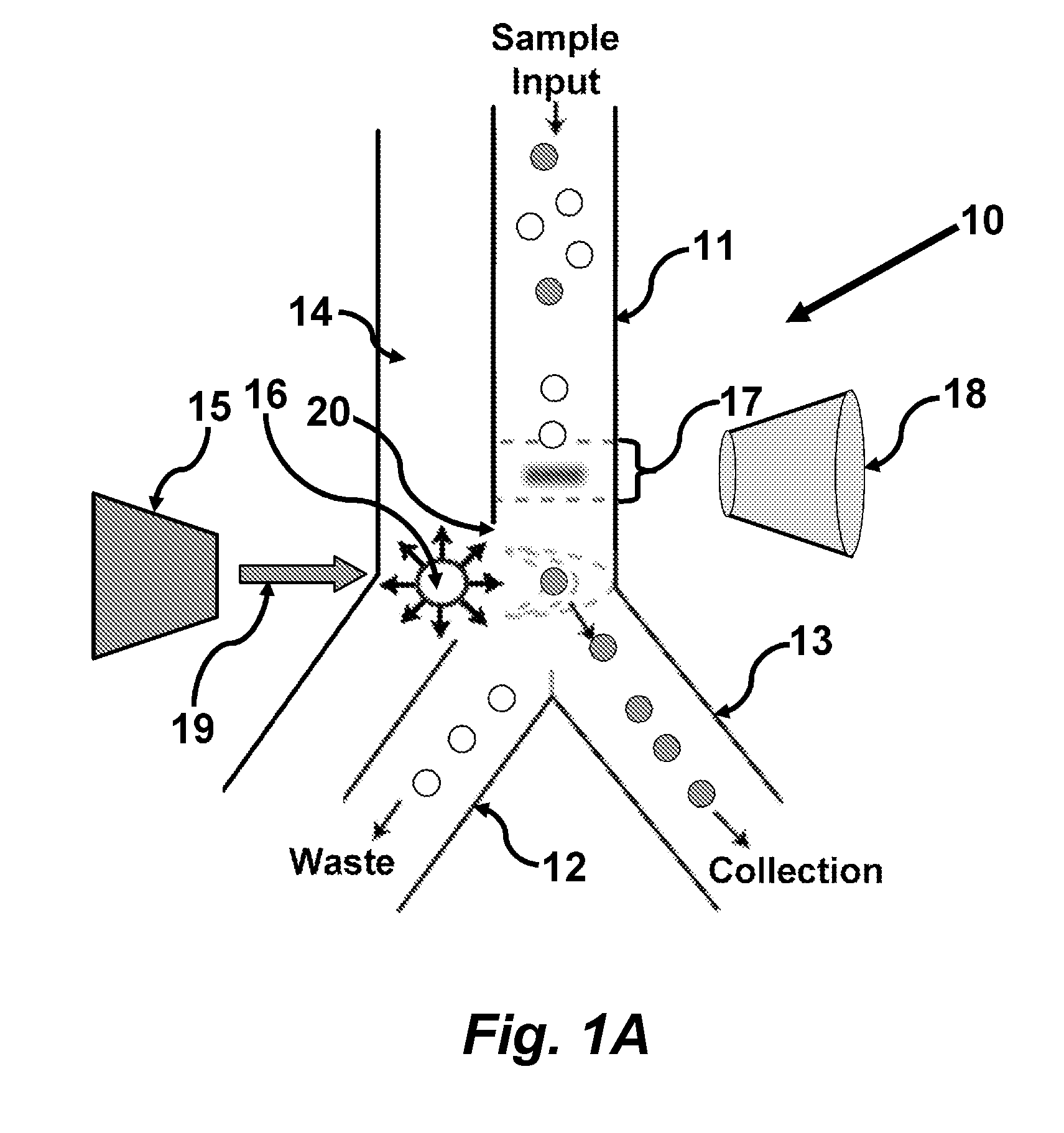
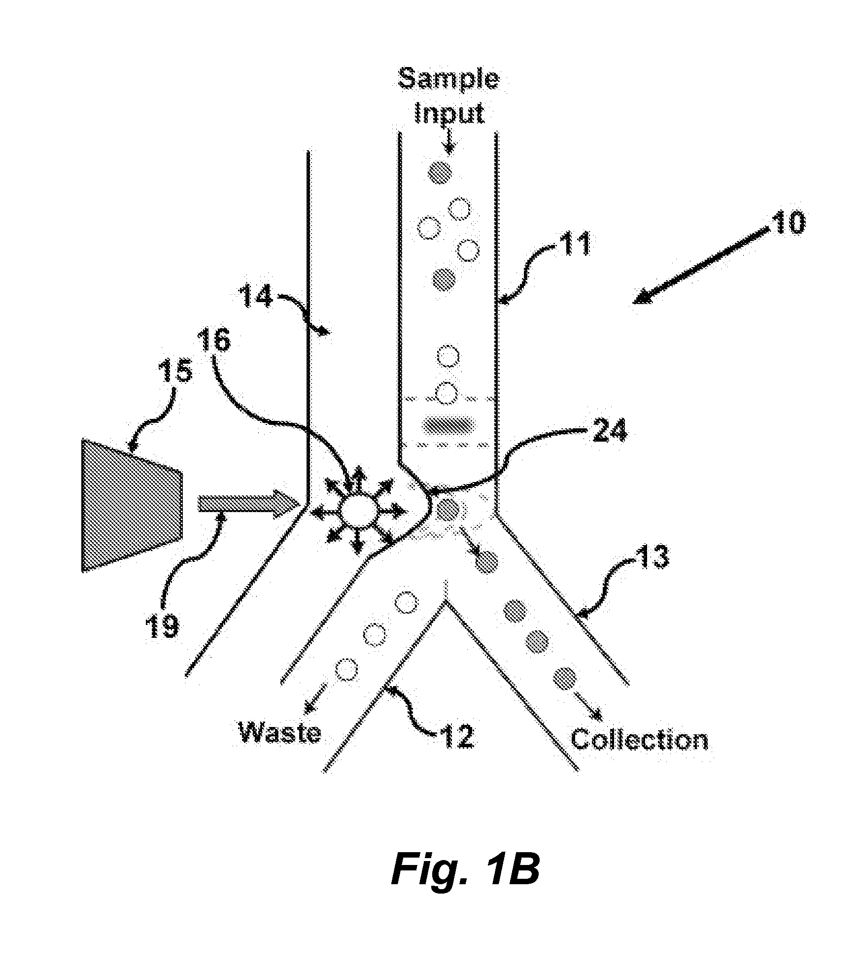
[0007]A novel and ultrafast microfluidic switching mechanism is described herein. Driven by laser pulse induced cavitation bubbles the switching mechanism permits the fabrication of microfluidic fluorescence activated cell sorters (FACS) capable of sorting at a speeds higher than 10,000 cells / sec. The sorters can be fabricated using monolayer PDMS channels to operate and no mechanical pumps and valves are required for the sorting function. This provides excellent compatibility with standard PDMS based microfluidic chips or platforms that have been widely applied in the past ten years for advancing various fields in biology [11-16].
[0009]In certain embodiments this invention provides a pulsed-laser triggered microfluidic switching mechanism that can achieve a switching time of 70 μs, or even shorter by using a harder microfluidic PDMS (or other flexible / elastic) channel. The switching mechanism permits the fabrication of FACS capable of sorting at a speed higher than 10,000 cells / sec. This switching speed is two orders of magnitude shorter than that of the fastest switching mechanism utilized in previous μFACS.

Problems solved by technology

However, these droplet-based sorting systems are often open and have several intrinsic drawbacks.
Contamination from the environment, operators, and samples are major issues for downstream cell culture and analysis.
Cell loss during transfer is also hard to prevent.
Furthermore, a microfluidic approach is advantageous for handling small numbers of cells (100-100,000) with high yield, which is difficult to achieve with conventional FACS.
Although a variety of different physical on-chip switch mechanisms have been proposed, none has simultaneously satisfied the requirements of high throughput, purity, and recovery of live, unstressed mammalian cells (see, e.g., Applegate et al.
Unfortunately, this method is limited by the difficulty of maintaining cell viability under high electric fields, particularly for eukaryotic cells, and by buffer incompatibilities.
However, because of the slow pneumatic mechanical switch and the relatively large volume of fluid displaced in every switch cycle, cell sorting demonstrations using hydrodynamic switching are slow.
However, this sorting speed is still 1˜2 orders of magnitude slower than commercial FACS.

Method used


Image

  • Pulsed laser triggered high speed microfluidic switch and applications in fluorescent activated cell sorting
  • Pulsed laser triggered high speed microfluidic switch and applications in fluorescent activated cell sorting
  • Pulsed laser triggered high speed microfluidic switch and applications in fluorescent activated cell sorting

Examples


example 1

Performance of a μFACS Using a Pulsed Laser Switch

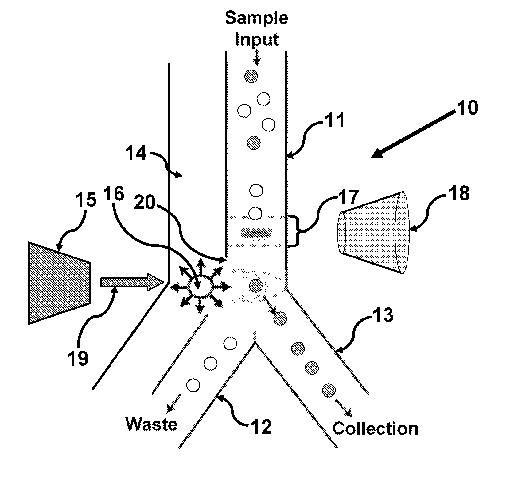
[0080]FIGS. 15A and 15B schematically illustrate a pulsed laser triggered fluorescence activated microfluidic cell sorter incorporating the switching device described herein. The device consists of a main microchannel (or sample channel) with two outlets, collection and waste. Using sheath flow focusing, the input particles are focused slightly off the centerline of the main channel and go into the waste channel. Fluorescent particles are detected as they flow through the top of the Y junction. This triggers a laser pulse focused through a high N.A. objective lens into the pulsed channel running in parallel with the main channel. The focused laser pulse induces optical breakdown of the liquid medium and the subsequent cavitation bubble. As the bubble expands, the surrounding liquid is pushed away and squeezed through the nozzle opening into the main channel. This liquid jet deflects the particle flow into the collection channel.

[0081...


PUM


Abstract

In certain embodiments this invention provides a pulsed-laser triggered microfluidic switching mechanism that can achieve a switching time of 70 μs. This switching speed is two orders of magnitude shorter than that of the fastest switching mechanism utilized in previous μFACS.

Description

CROSS-REFERENCE TO RELATED APPLICATIONS[0001]This application claims benefit of and priority to U.S. Ser. No. 61 / 087,039, filed Aug. 7, 2009, and to U.S. Ser. No. 61 / 232,416, filed Aug. 8, 2009, both of which are incorporated herein by reference in their entirety for all purposes.STATEMENT OF GOVERNMENTAL SUPPORT[0002]This invention was made with Government support under Grant No. NCC2-1364, awarded by the Center for Cell Mimetic Space Exploration (CMISE), a NASA URETI. The Government has certain rights in this invention.FIELD OF THE INVENTION[0003]The present invention relates to the field of microfluidics. In certain embodiments a pulsed laser triggered high speed microfluidic switch is provided.BACKGROUND[0004]Benchtop flow cytometers are the current standard for high speed, multi-parametric cell sorting. However, these droplet-based sorting systems are often open and have several intrinsic drawbacks. Contamination from the environment, operators, and samples are major issues for...

Claims


Application Information

Patent Timeline
IPC IPC(8): F15D1/00
CPCB01L3/502738G01N2015/149B01L2200/0636B01L2200/0652B01L2300/0816B01L2300/0864B01L2300/123B01L2400/0442B01L2400/0454B01L2400/0622B01L2400/0655F16K99/0001F16K99/0026F16K99/0028F16K99/004F16K99/0061F16K2099/0084G01N15/1459B01L3/502761Y10T137/0391Y10T137/2224G01N15/149
Inventor CHIOU, PEI-YUWU, TING-HSIANG
Owner RGT UNIV OF CALIFORNIA
Learn More