
Optical System with Movable Lens for Ophthalmic Surgical Laser

Active Publication Date: 2011-02-03
ALCON INC
View PDF47 Cites 68 Cited by
  • Summary
  • Abstract
  • Description
  • Claims
  • Application Information

AI Technical Summary

Benefits of technology

[0016]In some implementations the movable lens of the lens group is movable in a Z moving range to reduce a first aberration measure by at least a movable percentage P(movable), wherein the first aberration measure is one of a spherical aberration coefficient a40, an RMS wavefront error ω, and a focal spot radius rf; and the movable percentage P(m

Problems solved by technology

These procedures use manual instruments, ultrasound, heated fluids or lasers and tend to have significant drawbacks, including the need to enter the eye with probes in order to accomplish the fragmentation, and the limited precision associated with such lens fragmentation techniques.
These relatively long pulses deposit relatively large amounts of energy into the surgical spots, resulting in considerable limitations on the precision and control of the procedure, while creating a relatively high level of risk of unwanted outcomes.
As such, these designs do not offer solutions for the considerable challenges of performing surgery on the lens of the eye.

Method used


Image

  • Optical System with Movable Lens for Ophthalmic Surgical Laser
  • Optical System with Movable Lens for Ophthalmic Surgical Laser
  • Optical System with Movable Lens for Ophthalmic Surgical Laser

Examples


Embodiment Construction

ers.

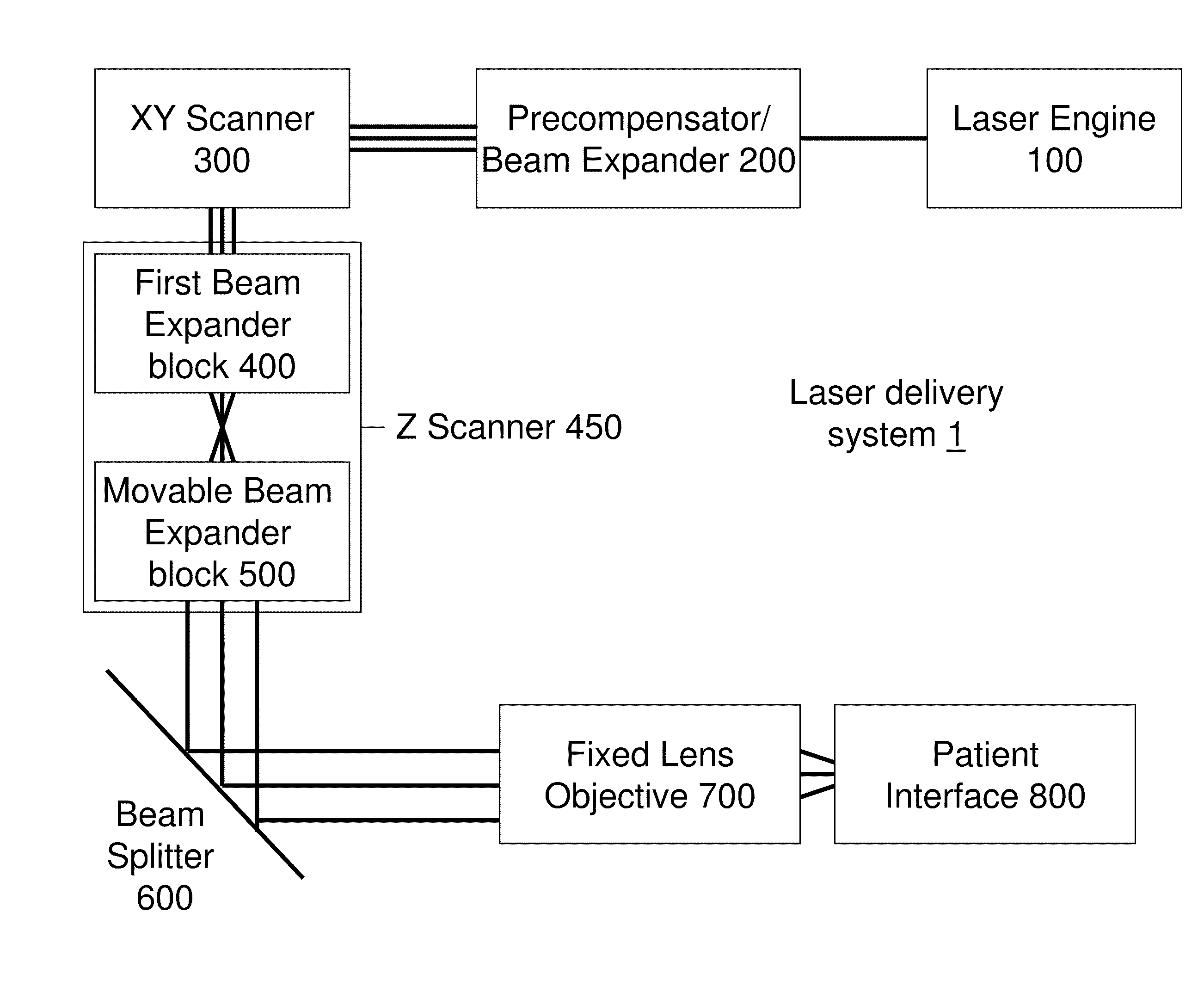
[0038]FIG. 10 illustrates a table of configurations containing 0, 1, or 2 Z depth Scanner and 0, 1, or 2 NA modifiers.

[0039]FIGS. 11A-C illustrate an XY Scanner with 2, 3, and 4 scanning mirrors.

[0040]FIGS. 12A-D illustrate an aberration as a function of a numerical aperture and the corresponding optical numerical aperture NAopt(z) as a function of the Z focal depth.

[0041]FIGS. 13A-B illustrate two settings of the First Beam Expander block 400 and the Movable Beam Expander block 500.

[0042]FIG. 14 illustrates the intermediate focal plane of the Z Scanner 450.

[0043]FIG. 15 illustrates an implementation of the Objective 700.

[0044]FIG. 16 illustrates a curved focal plane in the target region.

[0045]FIG. 17 illustrates a nomogram of the XY Scanner inclination angle.

[0046]FIG. 18 illustrates a nomogram of the Movable Beam Expander position.

[0047]FIG. 19 illustrates steps of a computational control method.

DETAILED DESCRIPTION

[0048]Some embodiments of the present invention include system...


PUM


Abstract

An eye-surgical laser system includes a laser source, to generate a laser beam, an XY scanner, to scan a focal spot of a received laser beam in an XY direction essentially transverse to an optical axis of the laser system, and a lens group, disposed in the optical path between the laser source and the XY scanner, to receive the laser beam generated by the laser source, to precompensate an aberration of the laser beam, and to forward the precompensated laser beam to the XY scanner, the lens group having a movable lens, movable in a Z direction along an optical axis.

Description

FIELD OF INVENTION[0001]This invention relates to a system for surgery of the anterior segment of the eye with a femtosecond laser, more particularly to embodiments minimizing optical distortions of the laser beam while scanning and focusing the laser beam into the eye.BACKGROUND[0002]This application describes examples and embodiments of techniques and systems for laser surgery within the anterior segment of the eye the crystalline lens via photodisruption caused by laser pulses. Various lens surgical procedures for removal of the crystalline lens utilize various techniques to break up the lens into small fragments that can be removed from the eye through small incisions. These procedures use manual instruments, ultrasound, heated fluids or lasers and tend to have significant drawbacks, including the need to enter the eye with probes in order to accomplish the fragmentation, and the limited precision associated with such lens fragmentation techniques.[0003]Photodisruptive laser tec...

Claims


Application Information

Patent Timeline
IPC IPC(8): A61F9/007A61B18/20
CPCA61F9/008A61F9/0084A61F2009/00889A61F2009/0087A61F2009/00872A61F2009/00851G02B26/08G02F1/29
Inventor RAKSI, FERENCBUCK, JESSE
Owner ALCON INC
Learn More