Burner of a gas turbine

a gas turbine and burner technology, applied in the direction of burners, combustion processes, lighting and heating apparatuses, etc., can solve the problems of low frequency instabilities with a frequency less than 30 hz, inability to deal with low frequency instabilities, and amplified combustion instabilities

Inactive Publication Date: 2011-02-03
ANSALDO ENERGIA IP UK LTD
View PDF12 Cites 10 Cited by
  • Summary
  • Abstract
  • Description
  • Claims
  • Application Information

AI Technical Summary

Benefits of technology

[0017]A burner of a gas turbine is disclosed including at least two part cone shells arranged offset with respect to one another and defining a cone shaped chamber with longitudinal tangential slots for feeding air therein, and a lance carrying at least a liquid fuel nozzle arranged centrally in the cone shaped chamber. A portion of the nozzl

Problems solved by technology

Nevertheless, when the liquid fuel jet cross-section is too small, it withstands large asymmetrical centrifugal forces because the liquid fuel jet can not reliably stay within the equally small vortex core and misses the centre, with large gradients of circumferential velocity, which then can prevent it from staying at the vortex core.
These fluctuations can lead to combustion instabilities that are amplified in the burner and combustion chamber downstream of the burner.
Combustion instabilities can influence both the lifetime and noise emission

Method used


Image

  • Burner of a gas turbine
  • Burner of a gas turbine
  • Burner of a gas turbine

Examples


Embodiment Construction

[0027]An aspect of the disclosure provides a burner with which combustion instabilities are limited and thus noise, in particular low frequency noise, can be reduced.

[0028]A further aspect of the disclosure provides a burner in which a liquid fuel jet can be injected into the vortex core.

[0029]Another aspect of the disclosure provides a burner that can have a longer lifetime with respect to traditional burners.

[0030]The burner in exemplary embodiments of the disclosure has a lance with a small angle with defined proportions that can allow a liquid jet to be generated that has a cross-section larger than the cross-section of the passage defined by the lance, but does not open forming a fuel cone. This allows a lance having small-cross-section to be manufactured, increasing ease of assembly and reducing lance complexity.

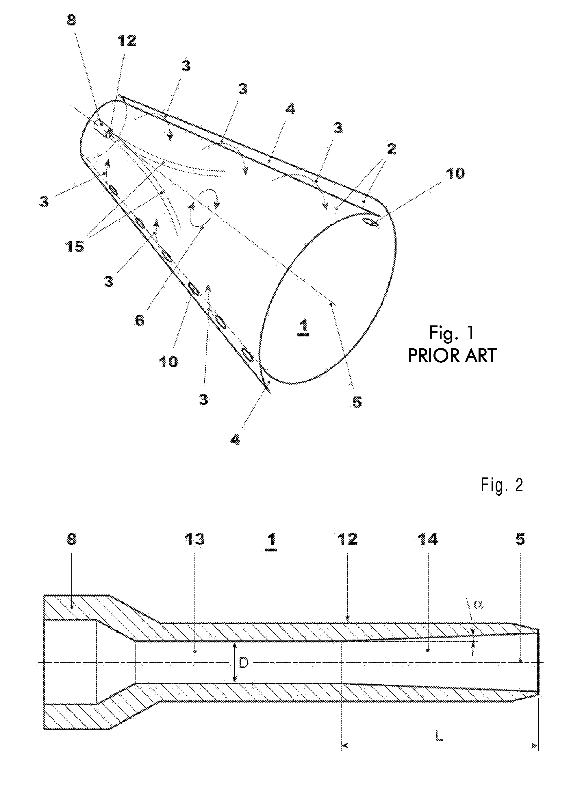
[0031]The disclosure relates to a burner of a gas turbine. The structure of the burner has two part cone shells 2 arranged offset with respect to one another and defin...


PUM


Abstract

The burner of a gas turbine includes two or more part cone shells arranged offset with respect to one another and defining a cone shaped chamber with longitudinal tangential slots for feeding air therein. A lance carrying a liquid fuel nozzle arranged centrally in the cone shaped chamber is also provided. A portion of the nozzle facing the cone shaped chamber is divergent in shape. A diffuser angle (α) between the wall of the nozzle and a longitudinal axis of the cone shaped chamber is less than 5°. A diverging portion of the nozzle has a diffuser length to nozzle diameter ratio comprised between 2-6. The nozzle diameter is the smaller diameter of the diverging portion.

Description

RELATED APPLICATION[0001]This application claims priority under 35 U.S.C. §119 to European Patent Application No. 09166907.7 filed in Europe on Jul. 30, 2009, the entire content of which is hereby incorporated by reference in its entirety.FIELD[0002]The present disclosure relates to a burner of a gas turbine.BACKGROUND INFORMATION[0003]FIG. 1 shows a known burner. This burner has a cone shaped chamber 1 defined by two part cone shells 2 wherein air 3 can be introduced through slots 4.[0004]The air generates in the centre of the cone shaped chamber 1 (i.e. along the axis 5 of the cone shaped chamber 1) a zone of larger vortices 6 (the vortex core).[0005]A lance 8 is provided along the axis 5 to inject a thin liquid fuel jet 15 into the cone shaped chamber 1. In particular the liquid fuel jet 15 can be injected into the vortex core 6 to mix with the air and form a combustible mixture.[0006]Nevertheless, when the liquid fuel jet cross-section is too small, it withstands large asymmetri...

Claims


Application Information

Patent Timeline
IPC IPC(8): F23C7/00
CPCF23C2900/07002F23C2900/07021F23R2900/00014F23D17/002F23R3/286F23D11/38
Inventor SCHIESSEL, PIRMINSCHUERMANS, BRUNOPAPA, ZDENKOEMBERGER, NORBERTEROGLU, ADNANCONZELMANN, RAINERTENTORIO, LUCA
Owner ANSALDO ENERGIA IP UK LTD
Why Eureka
Try Eureka