
Animal trap

Inactive Publication Date: 2011-02-03
HOVEY DAVID C
View PDF52 Cites 13 Cited by
  • Summary
  • Abstract
  • Description
  • Claims
  • Application Information

AI Technical Summary

Benefits of technology

[0029]It is an object of the instant invention to provide a new and improved animal trap, particularly for rodents, wherein the trap is shielded to enhance safety for people and pets and allowing one to empty the trap without touching a dead animal.
[0030]It is an object of this invention to provide an animal trap which, while capable of easy springing by an animal, may be handled with little danger of it being sprung accidentally, and which if so sprung, offers no danger to the fingers or hands of the user.
[0031]It is another object of this invention to provide an animal trap, particularly a large rat trap, wherein the means for activating the trap uses a leverage system or an electric motor that easily overcomes the large resistance created by the powerful springs used in such a rat trap.

Problems solved by technology

Unfortunately, there are many disadvantages connected with this type of trap.
For example, there is a risk of a user hurting his fingers while trying to set the mouse trap in the cocked position.
Additionally, the locking devices for such traps are very sensitive and apt to accidentally unlock and release the striker.
Because of the open exposure of the trap mechanism, it is dangerous to use a spring-loaded type of trap in places where there are small children and pets that can accidentally trigger the trap and catch their extremities therein.
Additionally, many of the prior art traps are hazardous to the hands and fingers of the trap setter since it is usually necessary to place the hands and fingers in the path of the spring mounted jaw during setting.
The catch mechanism can be unreliable or difficult to secure and the catch mechanism releases the jaw to snap shut before the person setting the trap can remove all his / her body portions from the path of the jaw.
Often, a catch mechanism may be too sensitive to be usable or too insensitive to respond to rodent approaches or taking the bait on the trap.
Yet another problem associated with conventional type traps is that the mechanism and the method used to trip or release the striker are unreliable.
Another problem associated with conventional type traps are that rats and mice are especially attracted to peanuts and peanut butter.
Attempting to attach these type baits to a conventional trap's bait station is difficult, messy and hazardous.
Another problem frequently encountered with known traps, is that the release of the trapped animal from the trap is usually a messy, unsanitary, and difficult process.
This entails the unsanitary act of touching the jaw in the vicinity of the dead animal and sometimes even requires touching the animal itself.
Since rodents are noted carriers of germs and disease, it is completely undesirable to require a trap user to manipulate the trap in any way which places the user's hands in the area of the captured rodent.
Moreover, because a captured rodent is usually severely injured, such a trapped animal usually presents a gory sight that is not well-received by a squeamish user.
Another problem associated with known mousetraps is that the animal may approach the trap from different directions, thus limiting the effectiveness of the killing mechanism.

Method used


Image

  • Animal trap
  • Animal trap
  • Animal trap

Examples


Embodiment Construction

[0095]The illustrated animal trap, is designed primarily for trapping rodents such as rats or mice, however it may be used for fur-bearing animals or other pests that can be attracted into the trap. In its preferred and illustrated use it is designed to eliminate rats.

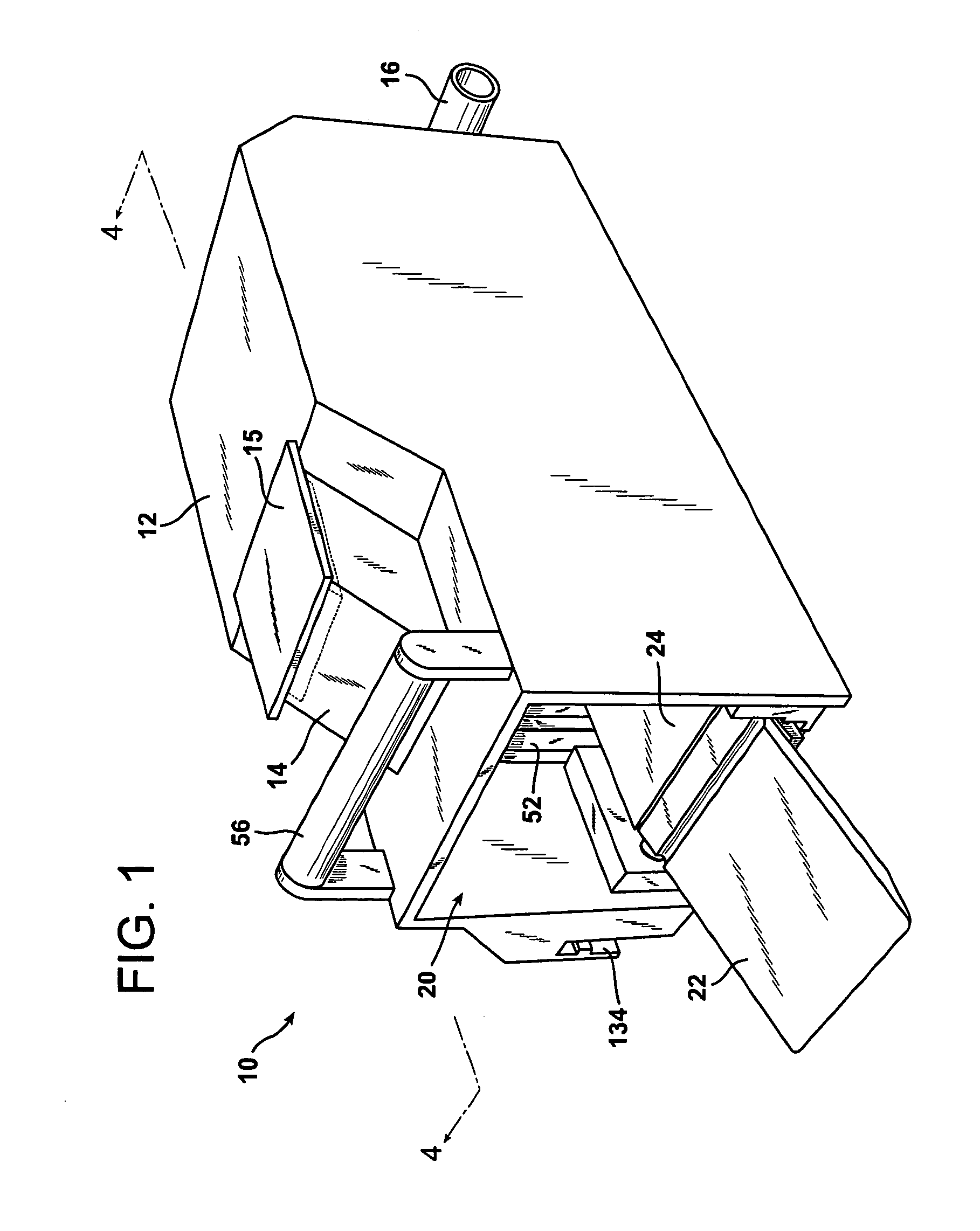
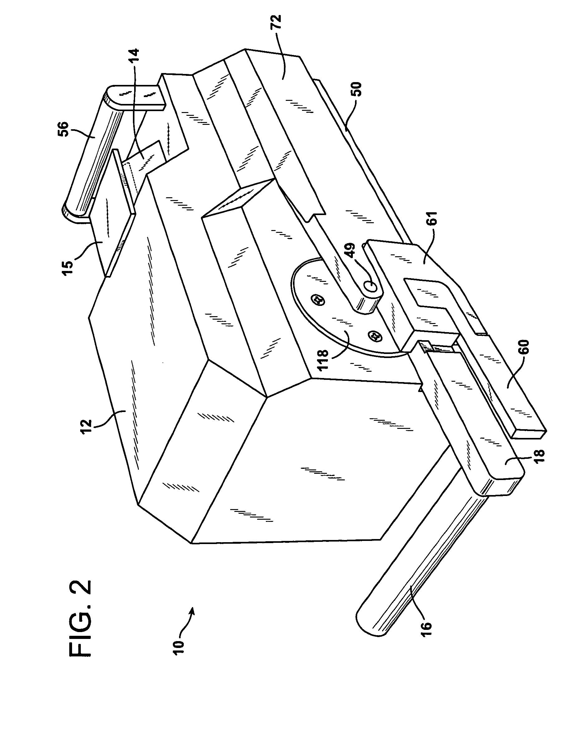
[0096]Referring to the Figures, in particular FIGS. 1 and 2, the animal trap of this invention 10 includes an enclosure 12. The enclosure 12 has one portion opened 20 for entrance of an animal 128 (see, for example FIGS. 4 and 5) into the trap 10. The remaining portions of the enclosure 12 cover the trap mechanism and “kill area” and form a substantially complete enclosure therefore except for openings therein that cooperatively function with the trap mechanisms, openings that contribute to the functionality of the trap (see, for example FIGS. 3 and 4) or incidental openings that do not interfere with the function and benefits of the trap 10 of this invention.

[0097]The enclosure 12, as depicted in substantially all the...


PUM


Abstract

An animal trap having a jaw frame pivotally mounted to a base for pivotal movement between a cocked position and a sprung position. A spring means is provided for biasing the jaw frame towards the sprung position. A gear system is mounted proximate one side of the base that has a drive gear and a driven gear that are cooperatively engaged with each other. The driven gear is releasably engaged to the jaw frame when the jaw frame is in the sprung position. A lever means or electric motor is provided for the selective engagement with the drive gear.When the lever or electric motor is selectively engaged to the drive gear and is rotated, the drive gear is rotated causing the driven gear to rotate to thereby pivot the jaw frame to the cocked position. After the animal is trapped, the lever or drive gear is selectively engaged with the drive gear. This permits the jaw frame to be pivotally moved to the cocked position while simultaneously releasing the animal from the trap. An enclosure is provided for enclosing the trigger member and the catch means. The enclosure has an opening to the interior of the trap that is proximate the trigger member to permit the animal to enter the enclosure and step on the trigger member to spring the jaw frame. The trap has a bait container mounted to the exterior of the enclosure that the animal cannot get to but can clearly smell from the interior of the enclosure. Optionally, the trap includes a liner that coacts therewith and has a bait container.

Description

BACKGROUND OF THE INVENTION[0001]1. Field of the Invention[0002]This invention relates to an animal trap, preferably used to trap rodents such as mice and rats. More particularly, this invention relates to an improved animal trap that includes a trap mechanism which can be set without risking bodily harm, a handle that is remote from a jaw of the trap mechanism that can be used to set the trap and release and discard the trapped, dead animal and an enclosure for the trap mechanism that has a bait container exterior to the enclosure for ease of baiting and reuse of the bait.[0003]2. Description of the Related Art[0004]Animal traps, and in particular mouse traps have been designed in many ways throughout the years. The most popular conventional, mouse trap includes a bar that is spring-mounted to a wood base, the bar and the base forming jaws in which the bar can be moved from a cocked position to a released position when the mouse touches the trigger arm. A larger version may be used...

Claims


Application Information

Patent Timeline
IPC IPC(8): A01M23/30A01M23/00
CPCA01M23/30A01M23/08
Inventor HOVEY, DAVID C.
Owner HOVEY DAVID C
Learn More