
Fuel injector with an improved valve control arrangement

a fuel injector and valve control technology, applied in the direction of fuel injection apparatus, machine/engine, feed system, etc., can solve the problems of static leakage, waste of energy, actuator is not able to generate sufficient force to close an unbalanced valve, etc., to facilitate optimisation of the hydraulic system, increase the pressure, and optimise the speed of movement of the injection valve member

Active Publication Date: 2011-01-27
DELPHI TECH IP LTD
View PDF6 Cites 0 Cited by
  • Summary
  • Abstract
  • Description
  • Claims
  • Application Information

AI Technical Summary

Benefits of technology

[0004]In operation, to raise the valve needle and hence open the injection orifices the discharge valve is opened, under the direct control of the solenoid actuator. The fuel within the valve needle control chamber is then able to flow out to the low pressure drain via the SPO. Because the INO is present in the high pressure fuel supply line to the valve needle control chamber the pressure of the fuel within the valve needle control chamber is reduced and thus the downwards force applied to the valve needle, as a result of the fuel acting upon the distal thrust surface, is reduced. High pressure fuel is still acting on the medial thrust surface of the valve needle and the resulting upwards force applied to the valve needle thrust surface is greater than the downwards force applied to the valve needle and thus the valve needle starts to move upwards. When the injection orifices open the fuel within the chamber in the nozzle body flows out to an engine cylinder, which is at a relatively low pressure, and thus the fuel pressure within the annular chamber in the nozzle body reduces. As the pressure of the fuel within the annular chamber in the nozzle body reduces the upwards force acting on the valve needle reduces. However, at this point the upwards force acting on the thrust surface is still greater than the downwards force applied to the valve needle and thus the valve needle remains in a raised position and fuel injection through the injection orifices continues.
[0025]The provision of the restricted fuel supply passage facilitates faster filling of the injection valve member control chamber when the discharge valve is closed and thus results in faster closing of the valve member. In the first embodiment there is a delay between the discharge valve closing and the shut-off valve member moving to open the high pressure fuel supply line to the injection valve member control chamber because it takes some time for the shut-off valve member control chamber to fill with pressurised fuel, due to the restriction provided in the shut-off valve member control chamber fuel supply line. The ability to close the valve needle more quickly facilitates short duration injections. Also, the orifice of the restricted fuel supply passage provides an extra degree of freedom which allows better optimisation of the hydraulic system.

Problems solved by technology

It is necessary to use a hydraulically balanced discharge valve because a small solenoid actuator is used to control movement of the discharge valve and such an actuator is not able to generate sufficient force to close an unbalanced valve against the high pressure of the fuel within the valve needle control chamber acting against it.
A disadvantage of hydraulically balanced valves is that they suffer from static leak.
This static leak requires a higher pump capacity and results in wasted energy as pressurised fuel escapes to the low pressure drain.
As mentioned above, it is not possible to use an unbalanced valve as the force required to drive it could only be supplied by a larger solenoid actuator, which would not fit within the injector body, or by a different type of actuator, such as a piezo-electric actuator, which would be prohibitively expensive.
Also, the prior art control arrangement suffers from dynamic fuel leakage when the valve needle is raised.
The dynamic leakage is disadvantageous for the same reasons set forth above in respect to static leakage.
There is hence a conflict between the requirements for fast opening and fast closing of the valve needle.
Thus the prior art control arrangement is limited by suffering from undesirable levels of static and dynamic leakage and from having a relatively long delay time between actuation of the discharge valve and movement of the valve needle.
Also since the pressure of fuel passing through the fuel outlet passage is reduced the discharge valve can be unbalanced, thus eliminating static leakage, yet still operable by an actuator comparable to that used previously with a balanced discharge valve.
Preferably, wherein the shut-off valve member is unbalanced.
The shut-off valve member is unbalanced because there is a difference between the sectional area of the shut-off valve member exposed to a force from pressurised fuel causing the shut-off valve member to move in a first direction, for example downwards, and the sectional area of the shut-off valve member exposed to a force from pressurised fuel causing the shut-off valve member to move in a second direction, opposite to the first direction, for example upwards.
As the injection valve member moves upwards the volume of the injection valve member control chamber reduces and this tends to increase the pressure within it.
In the first embodiment there is a delay between the discharge valve closing and the shut-off valve member moving to open the high pressure fuel supply line to the injection valve member control chamber because it takes some time for the shut-off valve member control chamber to fill with pressurised fuel, due to the restriction provided in the shut-off valve member control chamber fuel supply line.

Method used


Image

  • Fuel injector with an improved valve control arrangement
  • Fuel injector with an improved valve control arrangement
  • Fuel injector with an improved valve control arrangement

Examples


Embodiment Construction

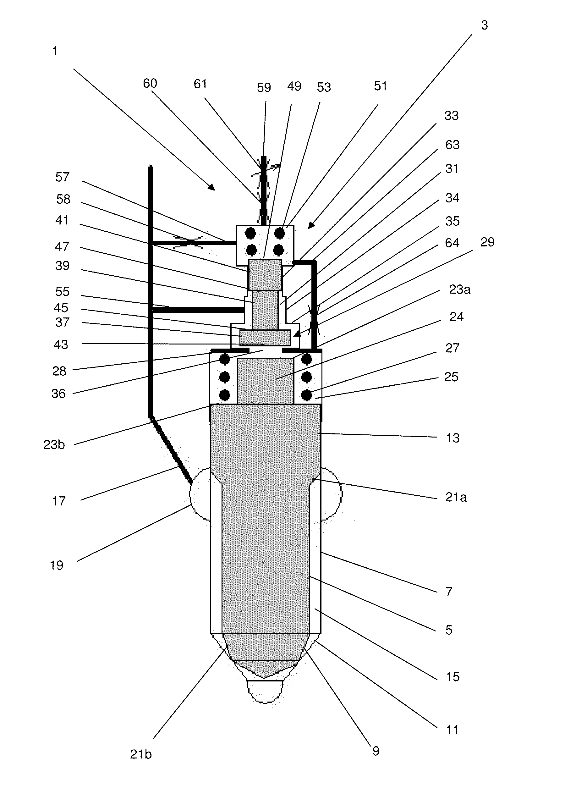
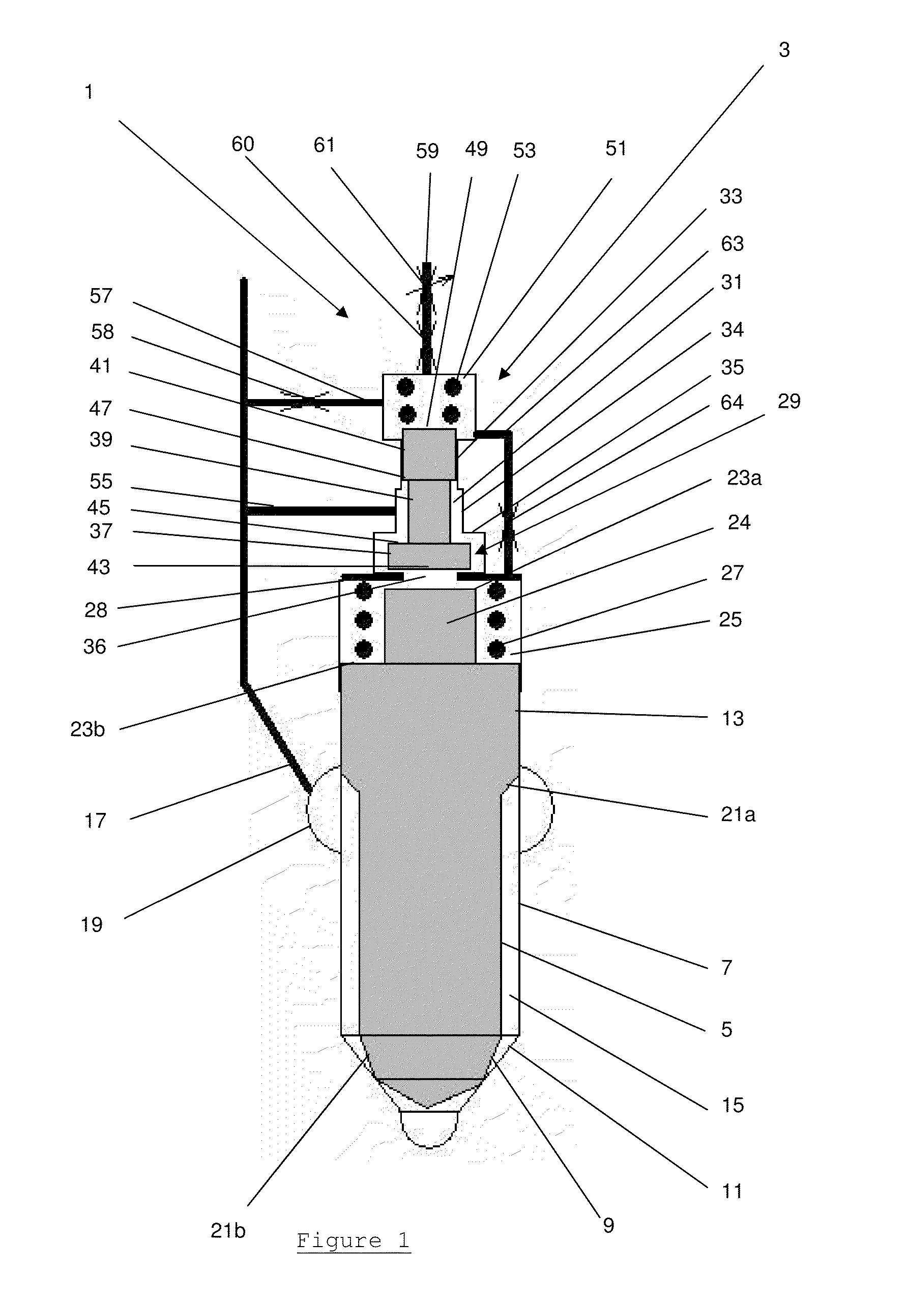
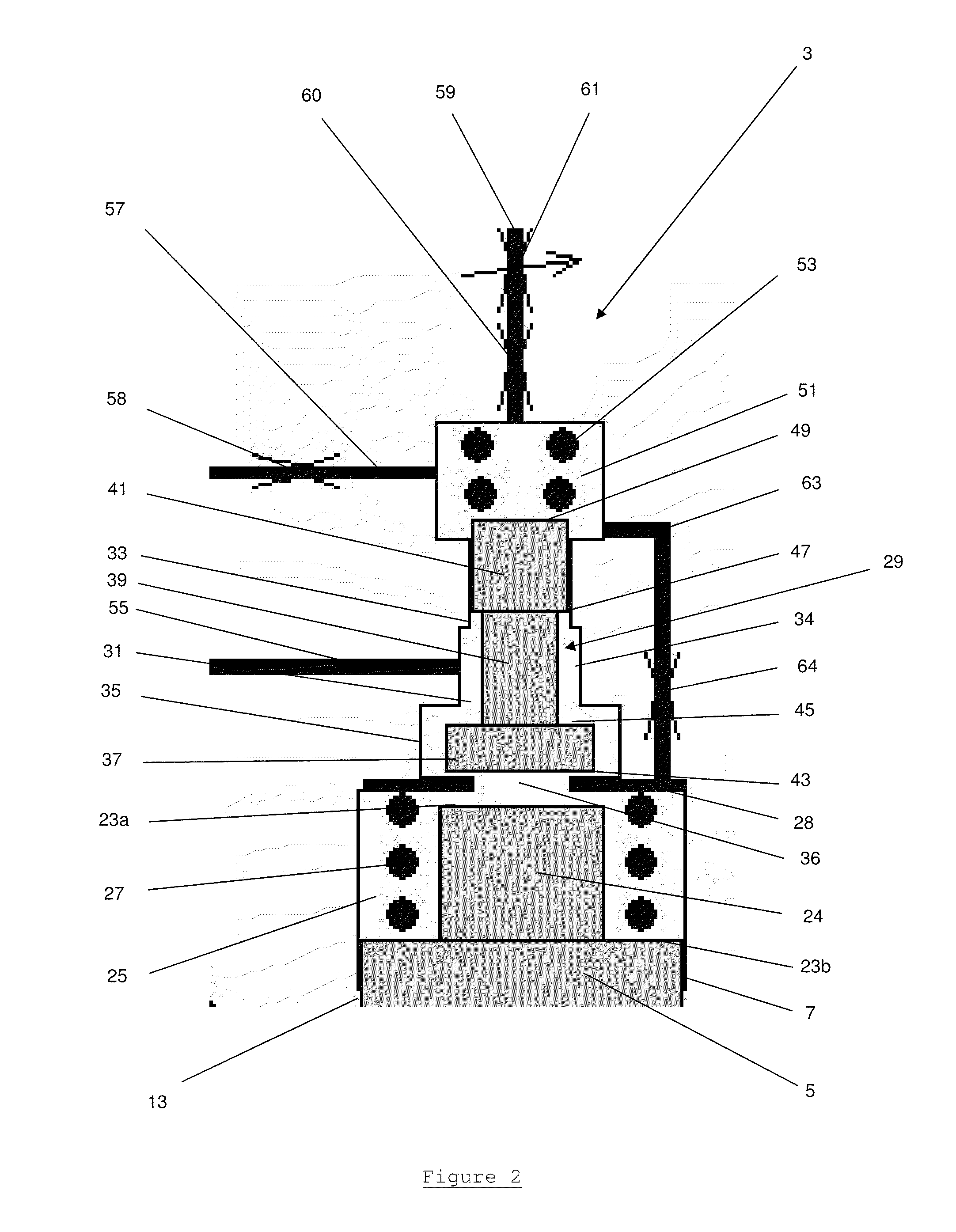
[0035]A fuel injector 1, as shown in FIG. 1, is provided with a valve needle control arrangement 3 according to a preferred embodiment of the present invention. The fuel injector 1 comprises a conventional arrangement of a needle valve having a valve needle 5 located within the injector nozzle body 7.

[0036]The valve needle 5 is elongate, has a circular cross-sectional profile and comprises at a lower end a valve face 9 which is complementary in shape to a valve seat 11 provided on the nozzle body 7, such that when the valve face 9 contacts the valve seat 11 a fluid-tight seal is formed between them.

[0037]Towards its upper end the valve needle 5 is provided with a guide surface 13 which engages with the nozzle body 7 in a manner such that the valve needle 5 can slide relative to the nozzle body 7. The clearance between the valve needle 5 and the nozzle body 7 is minimised in order to minimise the flow of pressurised fuel across the guide section 13 from a fuel supply chamber 15, loca...


PUM


Abstract

A fuel injector for a compression ignition internal combustion engine which comprises a fuel injection valve having an injection valve member which is moveable in use, under the influence of fuel pressure within an injection valve member control chamber acting upon it, between a closed position and an open position. The fuel injector further comprises a high pressure fuel supply passage to the injection valve member control chamber, and an actuator operable to open and close a discharge valve connected between the injection valve member control chamber and a fuel outlet passage to a low pressure reservoir or drain. A shut-off valve is provided in the high pressure fuel supply passage and the shut-off valve has a shut-off valve member which is moveable in use, under the influence of fuel pressure within a shut-off valve member control chamber acting upon it, between a closed position and an open position. The shut-off valve member control chamber is connectable to the low pressure reservoir or drain via the discharge valve, and a fuel transfer passage is provided between the injection valve member control chamber and the low pressure reservoir or drain.

Description

TECHNICAL FIELD[0001]The present invention relates to a fuel injector with an improved valve control arrangement for positioning a valve needle of a fuel injector in a position whereby injection of fuel occurs, and in a position whereby injection of fuel is prevented. In particular, the present invention relates to a valve control arrangement which utilises a shut-off valve to control the flow of high pressure fuel between a high pressure fuel supply and an injection valve needle control chamber in order to eliminate static leakage from the injector, reduce dynamic leakage and improve injector performance, particularly the robustness of the injector and the opening and closing speed of the valve needle.SUMMARY OF THE BACKGROUND[0002]It is known to control the movement of a valve needle within a fuel injector, to commence and cease fuel injection, by utilising a discharge valve operated by an actuator to control the pressure of fuel within a valve needle control chamber. A valve cont...

Claims


Application Information

Patent Timeline
Patent Type & Authority Applications(United States)
IPC IPC(8): F02M47/02F02M63/00
CPCF02M63/0029F02M47/025
Inventor LECLUSE, ERICENTERS, RICHARD DENIS JACQUES ALAINCHARLEUX, ERIC
Owner DELPHI TECH IP LTD
Learn More