
Method for the low-temperature pressure sintering

a low-temperature pressure sintering and pressure sintering technology, which is applied in the direction of soldering apparatus, semiconductor/solid-state device details, manufacturing tools, etc., can solve the problems of inability to mount the manufacturing and testing step cost-savingly, the entire unit is deformed, and the surrounded unit with integrated heat sink plate deformation, etc., to achieve optimized heat spreading, and small volume of thermosetting plasti

Active Publication Date: 2011-01-27
DANFOSS SILICON POWER
View PDF13 Cites 14 Cited by
  • Summary
  • Abstract
  • Description
  • Claims
  • Application Information

AI Technical Summary

Benefits of technology

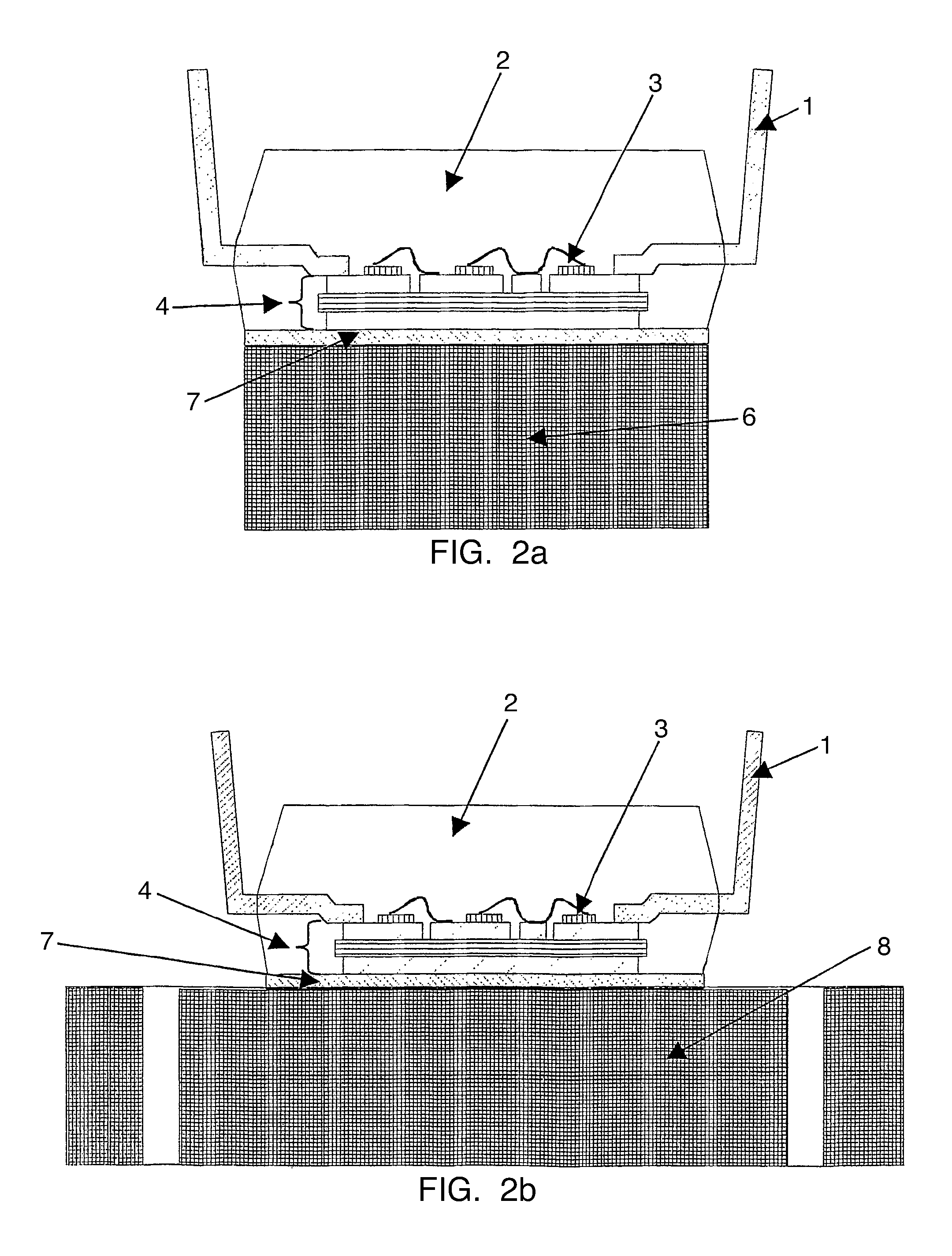
[0017]According to the invention, the following process steps are to avoid the disadvantages that have been mentioned and explicitly lead on the one hand to a reproducible convex deformation of the heat sink plate relative to a flat cooling body and on the other hand enable significant savings of the mold compound simultaneously with a correctly dimensioned heat sink plate.
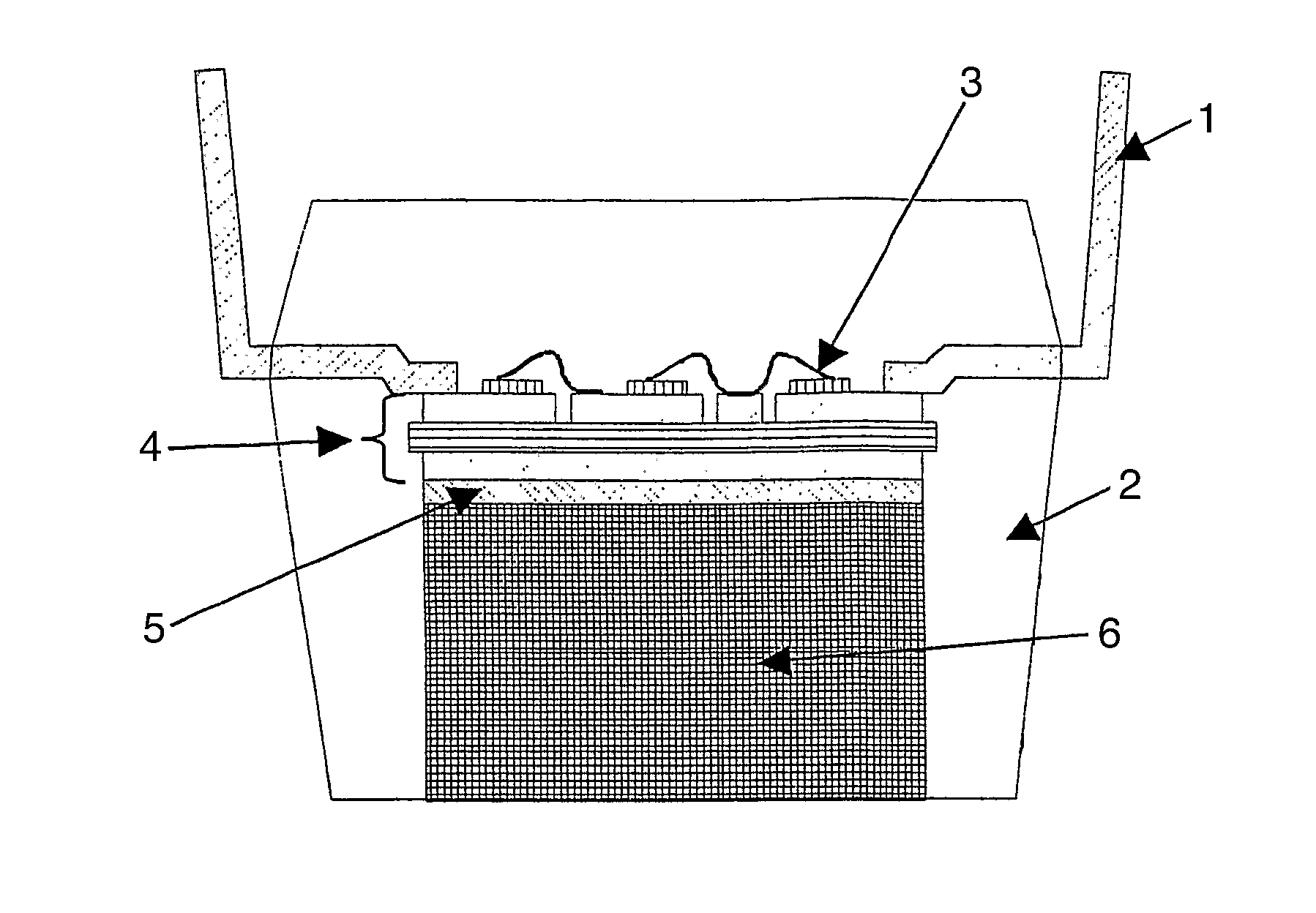
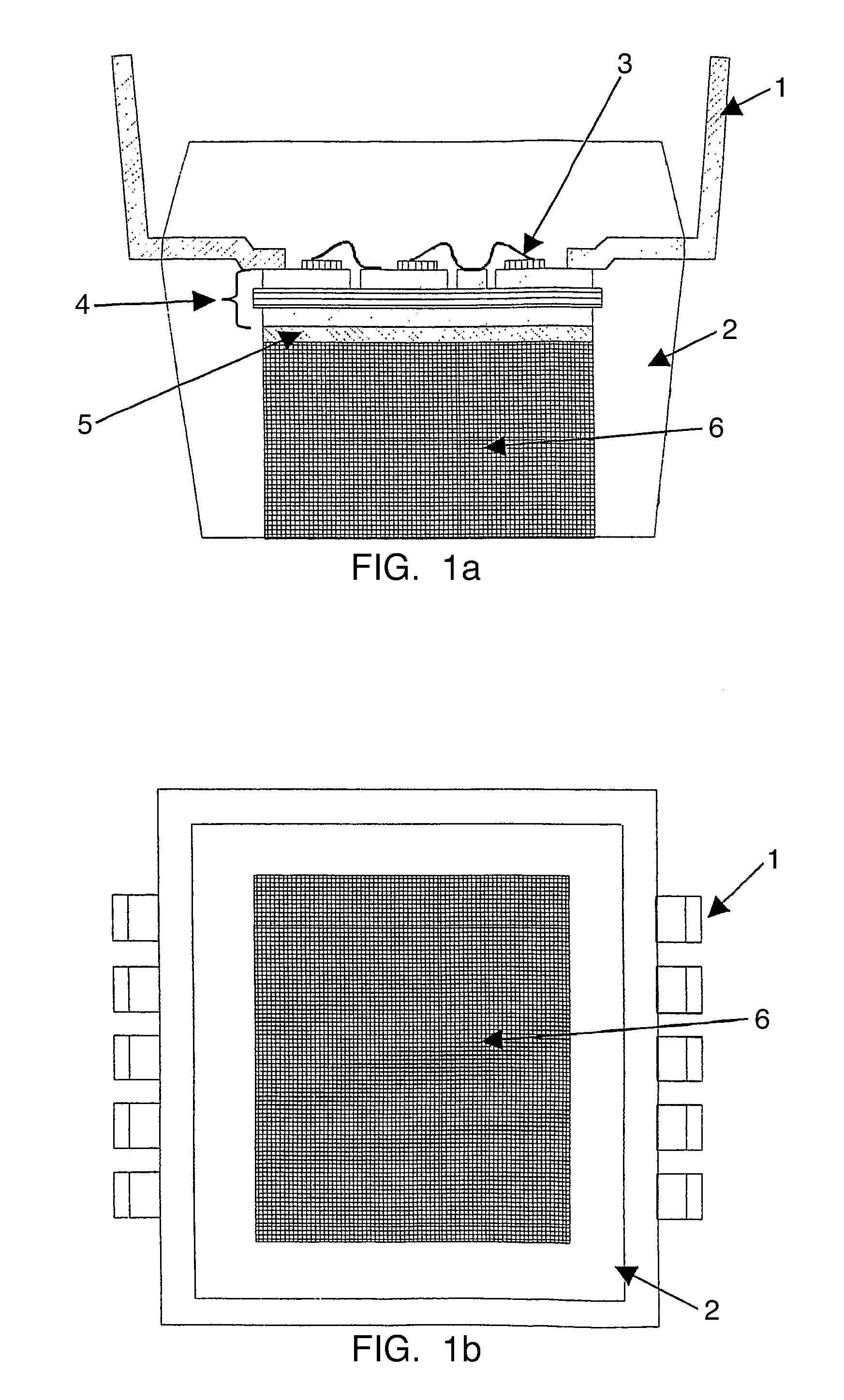
[0020]A deformation by mismatching of the thermosetting plastic and the populated substrate is now no longer the case. The volume of the enveloped substrate is markedly less, and the material and energy consumption is correspondingly more economic and ecological (see FIGS. 1a, 1b with FIGS. 2a, 2b).

Problems solved by technology

In the case of a series or parallel connection of several substrate unites (multi-substrate module) on only one heat sink plate, it is particularly disadvantageous that for reasons of economic yield, only single units that have been tested electrically as good units can be mounted on a joint heat sink plate.
This cost-saving manufacturing and testing step is not possible for mounting by means of silver pressure sintering, since the quasi-isostatic pressing of the unit during the sintering process would destroy the bond wires of the electrically wired unit.
Another disadvantage of the prior art that is resolved by the present invention is deformation of the surrounded unit with integrated heat sink plate as a result of large differences in expansion. a.)
The process described of shape-pressing (transfer molding) has the disadvantage for the entire unit that renewed heating to approx.

Method used


Image

  • Method for the low-temperature pressure sintering
  • Method for the low-temperature pressure sintering
  • Method for the low-temperature pressure sintering

Examples


Embodiment Construction

[0031]The heat sink plate is now bonded in another connection process, that is the silver sinter pressure technology, to the completed mold-enveloped body of the electronic unit (and stable in the long term) (FIGS. 2a, 2b). The connecting layer of the sintered silver typically has a thermal conductivity of about 250 W / mK and is thus thermally and mechanically far superior to any heat conducting paste and any adhesive and solder.

[0032]a. The heat sink plate can now be selected to have a sufficient size, that is to say at least identical to the substrate size (primary function; high thermal capacity) or identical with the mold-enveloped body, or preferably also larger than the mold-enveloped body (heat spreading and increase in the thermal capacity).

[0033]b. The pressure sintering technology connects by means of temperature and pressure. The pressure permits to press the heat sink plate into a bed (=lower press ram) with a smaller radius than results after the finished connection afte...


PUM

PropertyMeasurementUnit
temperatureaaaaaaaaaa
pressureaaaaaaaaaa
metallicaaaaaaaaaa

Abstract

A method for the low-temperature pressure sintering of at least one electronic unit to be contacted thermally, firmly connected mechanically, and located on a substrate, comprising the following steps: pressing the electronic unit using a mold enveloping matrix while sparing a connecting surface of the substrate for a heat sink connection, providing a heat sink plate, applying a sintering connecting layer onto the spared region of the connecting surface and / or onto to the region of the heat sink plate provided for contacting, and bonding of the heat sink plate to the substrate of the electronic unit in the region of the connecting surface using silver low-temperature pressure sintering technology.

Description

CROSS REFERENCE TO RELATED APPLICATIONS[0001]This application is entitled to the benefit of and incorporates by reference essential subject matter disclosed in International Patent Application No. PCT / DE2009 / 000050 filed on Jan. 16, 2009 and German Patent Application No. 10 2008 009 510.9 filed Feb. 15, 2008.FIELD OF THE INVENTION[0002]The invention relates to a method for pressure sintering. Electronic units in power electronics with one or more semiconductor components are usually manufactured using glued connections, soldered connections or silver pressure-sintering technology of the unprotected semiconductor to a primary circuit support. In the process, preferably ceramic circuit supports are used (so-called DCB substrates or direct copper bonded substrates).BACKGROUND OF THE INVENTION[0003]The substrates consist of a core of aluminum oxide or aluminum nitride having coefficients of expansion of 7-8 ppm / K and approx. 4 ppm / K. The substrate can also be a purely ceramic solution i...

Claims


Application Information

Patent Timeline
Patent Type & Authority Applications(United States)
IPC IPC(8): B23K1/20
CPCH01L21/50H01L2224/48227H01L23/49531H01L24/48H01L25/165H01L2224/29339H01L2224/48091H01L2224/48247H01L2224/48472H01L2224/8384H01L2224/85205H01L2924/0102H01L2924/15787H01L2924/19043H01L2924/12041H01L2924/01019H01L23/3735H01L2924/00014H01L2924/00H01L2924/00011H01L2924/181H01L2224/32225H01L2224/83205H01L2924/00012H01L2224/45099H01L2224/45015H01L2924/207
Inventor EISELE, RONALDKOCK, MATHIAS
Owner DANFOSS SILICON POWER
Learn More