
Liquid fuel storage tank for automotive vehicle

a technology for automotive vehicles and fuel storage tanks, which is applied in the direction of tank vehicles, transportation and packaging, transportation items, etc., can solve the problems of unacceptably rapid deterioration of internal tank components and exterior mounting devices, unsatisfactory noise and fuel pump starvation, and difficulty in securement of baffles, etc., to achieve significant reduction of noise due to sloshing, fuel pump starvation, and dynamic forces

Inactive Publication Date: 2011-01-27
FORD GLOBAL TECH LLC
View PDF19 Cites 38 Cited by
  • Summary
  • Abstract
  • Description
  • Claims
  • Application Information

AI Technical Summary

Benefits of technology

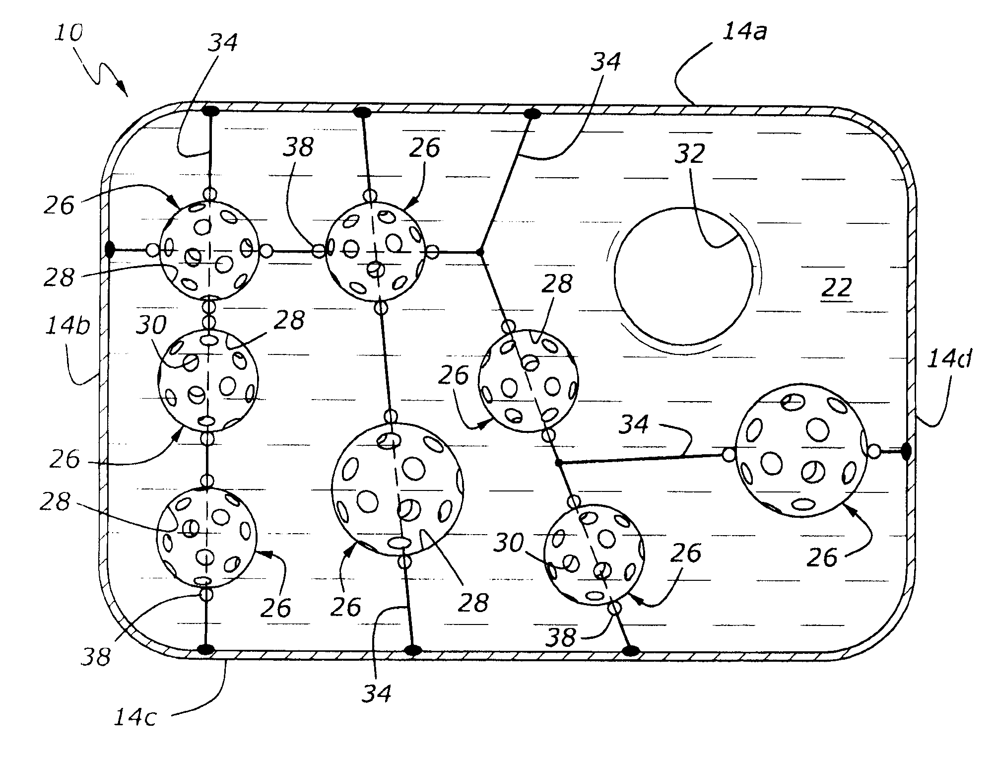
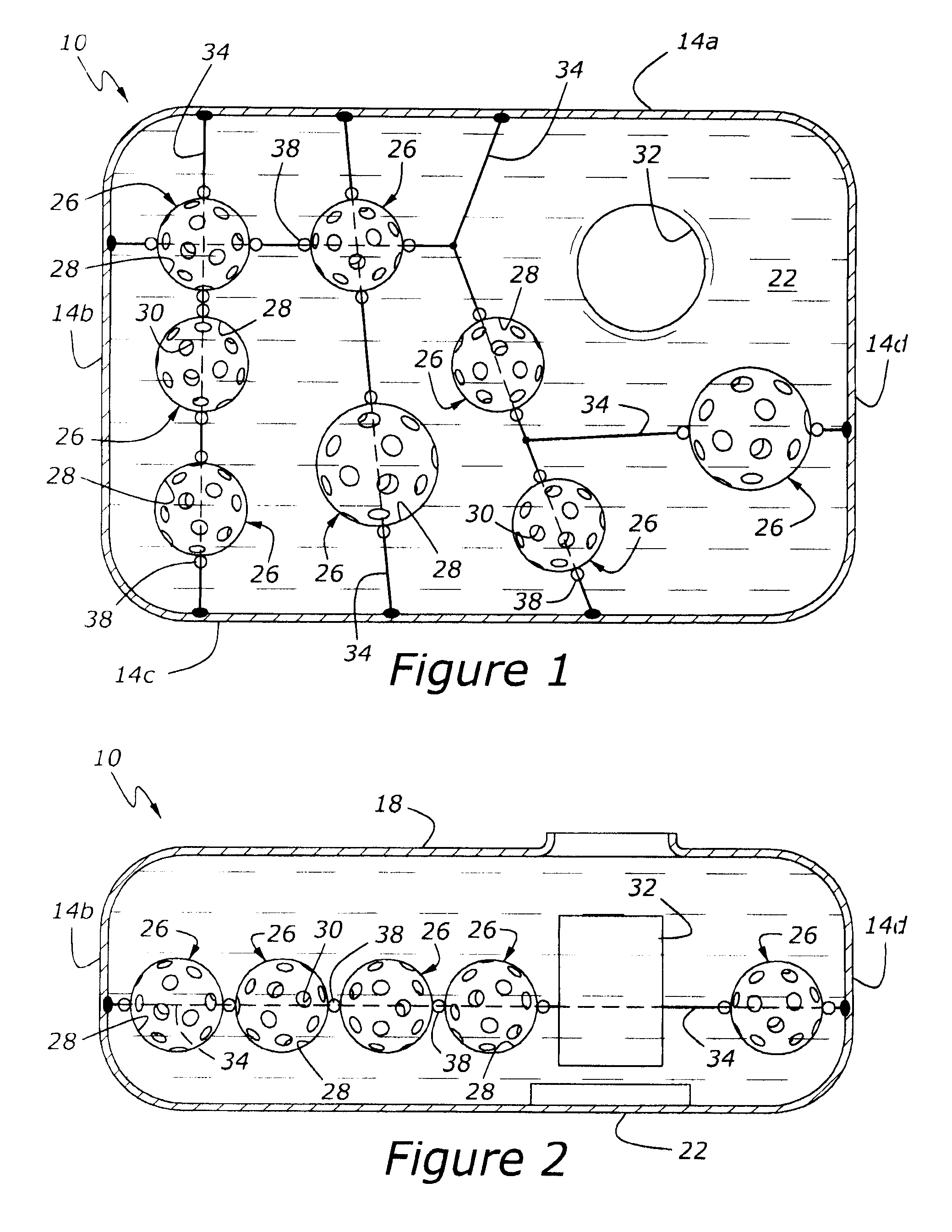
[0007]According to another aspect of the present disclosure, at least one of the anti-slosh bodies includes a generally ovoidal shell having a hollow interior with a number of ports extending through the shell. The anti-slosh bodies reduce sloshing by absorbing fluid energy and by breaking the fluid motion into many small trajectory motions. The curvature exhibited by the ovoidal shells allows the moving fluid to flow smoothly around the anti-slosh bodies, absorbing the energy and rendering the sloshing much quieter. The baffle effect produced by the anti-slosh bodies is not merely planar, but available in all directions since the walls of the anti-slosh bodies present themselves to the flow in every direction. The ports extending through the shells of the anti-slosh bodies allow the free flow of fuel at low frequency so that the fuel indicator can respond more accurately. This also helps to prevent fuel starvation when the fuel level is low in the tank.
[0015]It is yet another advantage of a liquid fuel storage tank according to the present disclosure that vent valves commonly used in fuel tanks will perform better in the absence of excessive sloshing.

Problems solved by technology

Because fuel inside an automotive liquid fuel tank moves freely, or, in the colloquial, “sloshes” while a vehicle is moving, undesirable noise and fuel pump starvation may occur, particularly when the fuel level is low.
Fuel sloshing may also cause problems with fuel level indicating devices, and in extreme cases may cause unacceptably rapid deterioration of internal tank components and exterior mounting devices, such as straps.
Although internal baffles have been used in fuel tanks for years, such baffles are difficult to secure, particularly in the case of plastic fuel tanks.
And, baffles generally exhibit poor performance and are expensive to design and tool for each tank.
Moreover, many of these problems are typically found with other types of tanks used to transport liquids.

Method used


Image

  • Liquid fuel storage tank for automotive vehicle
  • Liquid fuel storage tank for automotive vehicle
  • Liquid fuel storage tank for automotive vehicle

Examples


Embodiment Construction

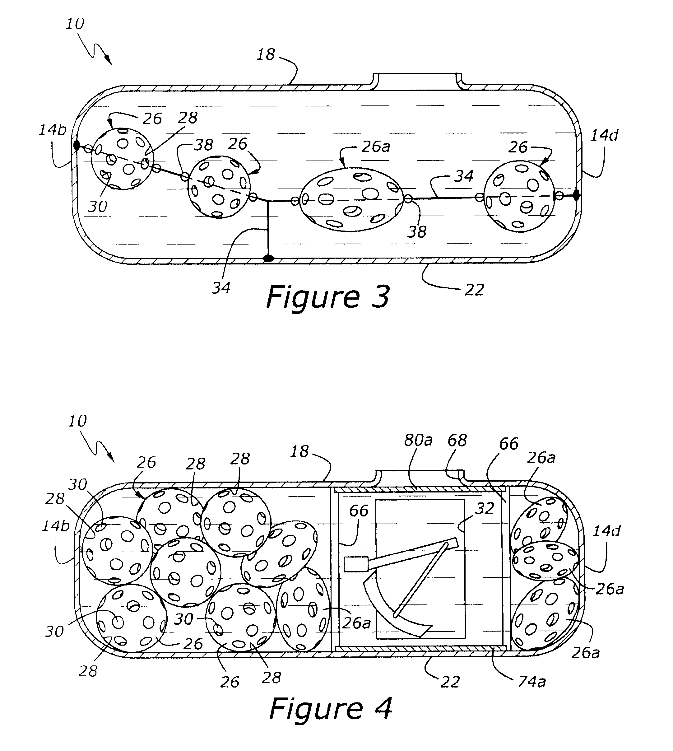
[0027]As shown in FIGS. 1 and 2, a fuel storage tank, 10, has a receiver defined by a number of perimeter walls including side walls 14a, 14b, 14c and 14d as well as upper perimeter wall 18 and lower perimeter wall 22. A number of generally ovoidal anti-slosh bodies, 26, are suspended within the receiver by a locator structure which cooperates with perimeter walls to confine anti-slosh bodies 26 within a predetermined part of the interior volume of the receiver. Each of the anti-slosh bodies 26 has a shell, 28, and a number of ports, 30, formed therein, to allow fuel to pass through anti-slosh bodies 26. Fuel tank 10 also includes a fuel delivery module, 32, which is shown in the various figures, and which includes an outlet (not shown) for fuel to leave tank 10 for transfer to the engine of a vehicle. Fuel delivery module 32 typically includes a fuel level sender, a pump, a filter, and various electrical and liquid connections for supplying fuel under pressure to a fuel line, (not ...


PUM


Abstract

A fuel storage tank for an automotive vehicle includes a receiver with a number of perimeter walls defining an interior volume for storing liquid fuel. A number of anti-slosh bodies are located within the receiver. A locator structure cooperates with perimeter walls to confine the anti-slosh bodies within a predetermined part of the interior volume.

Description

BACKGROUND OF THE DISCLOSURE[0001]1. Field of the Disclosure[0002]The present disclosure relates to a liquid transportation tank, and more particularly to a fuel storage tank for an automotive vehicle.[0003]2. Related Art[0004]Because fuel inside an automotive liquid fuel tank moves freely, or, in the colloquial, “sloshes” while a vehicle is moving, undesirable noise and fuel pump starvation may occur, particularly when the fuel level is low. Fuel sloshing may also cause problems with fuel level indicating devices, and in extreme cases may cause unacceptably rapid deterioration of internal tank components and exterior mounting devices, such as straps. Although internal baffles have been used in fuel tanks for years, such baffles are difficult to secure, particularly in the case of plastic fuel tanks. And, baffles generally exhibit poor performance and are expensive to design and tool for each tank. Moreover, many of these problems are typically found with other types of tanks used t...

Claims


Application Information

Patent Timeline
IPC IPC(8): B60P3/22B65D90/52
CPCB60K15/077B60K2015/0775B60K2015/03453
Inventor PALMA, RODOLFODONG, MIKEUSMAN, MOHAMMAD
Owner FORD GLOBAL TECH LLC
Learn More