Printing Machine

a printing machine and web-based technology, applied in the field of sheetfed or web-based printing machines, can solve the problems of creating security elements that are difficult if not impossible to copy with current equipment, unable to reproduce color images that cannot be printed with photocopiers or other photomechanical methods, and unable to achieve the effect of increasing the security of printing

Active Publication Date: 2011-01-27
KBA NOTASYS SA
View PDF29 Cites 22 Cited by
  • Summary
  • Abstract
  • Description
  • Claims
  • Application Information

AI Technical Summary

Benefits of technology

[0018]Another object of the invention is to propose a printing machine and a method employed by this machine that increases the security of the printing.
[0019]More specifically, it is an object of the invention to propose a printing system, particularly for paper securities, that can be incorporated into existing machines in a simple way.

Problems solved by technology

Thus, a latent color image is created that cannot be reproduced with a photocopier or other photomechanical methods.
According to other techniques known in the state of the art, use is made of a laser either to mark the substrate directly or to mark a layer applied to said substrate and thus create security elements that are impossible to reproduce using a photocopier or scanner.
Other security elements use optically variable devices (“OVDs”®) in the form of metalized patches (known as “foils”) or holograms and also moirés and other similar patterns, all of these being, on the one hand, very difficult if not impossible to copy with current equipment but also, on the other hand, very easy to check visually using appropriate means or with the naked eye.
However, one of the problems encountered when printing with optically variable ink lies in the fact that this ink is often used to print the value of the paper security (e.g. banknote), this value being generally indicated parallel to the length of the banknote.
Thus, existing machines need to be modified significantly, and this is of little economic benefit and increases the time needed for printing.

Method used


Image

  • Printing Machine
  • Printing Machine
  • Printing Machine

Examples


Embodiment Construction

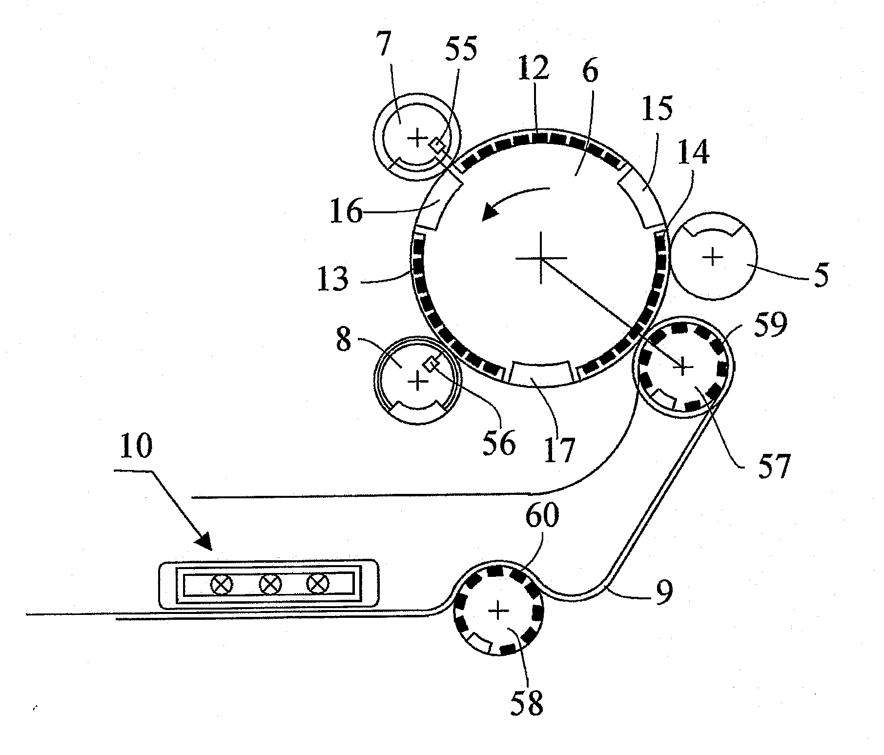
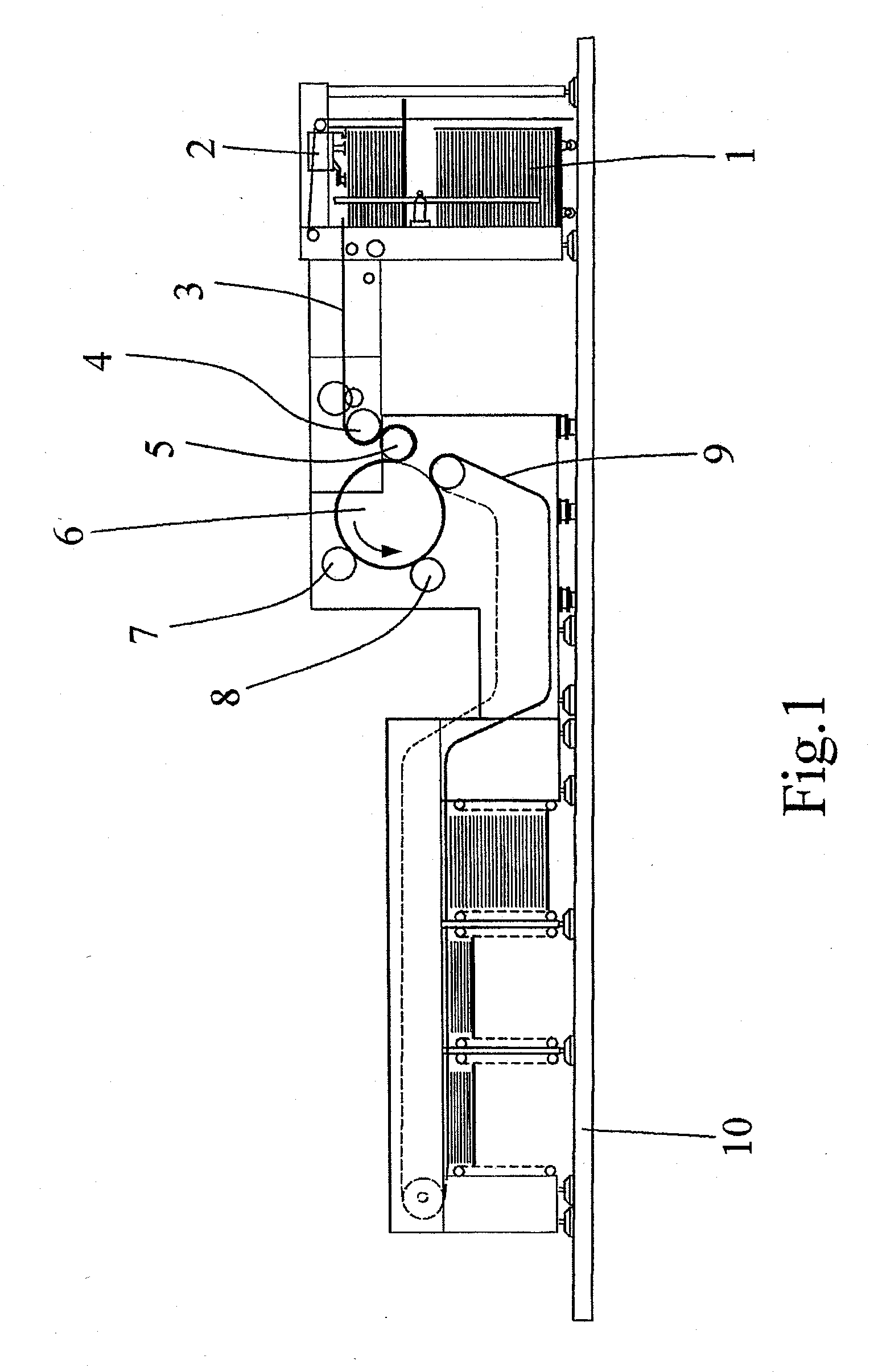
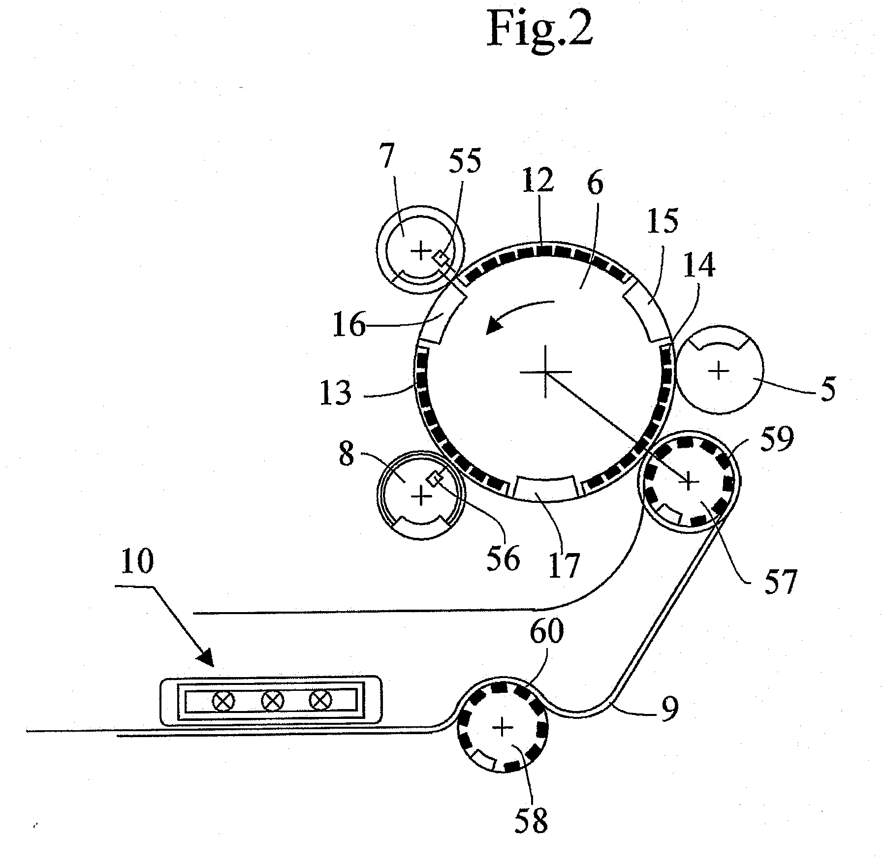
[0031]A conventional sheet-fed printing machine is described first of all with reference to FIG. 1. This known machine was described in detail in U.S. Pat. No. 6,109,172 and its content is incorporated by reference into this application inasmuch as regards the operating principle of a screen-printing machine. The machine comprises a magazine 1 containing sheets for printing, a feed device 2 for successively transferring sheets along the path 3 toward a feed cylinder 4, a transfer cylinder 5 for conveying the successive sheets onto an impression cylinder 6, two screen cylinders 7 and 8 with doctor blades and collaborating with the impression cylinder 6 and a chain gripper system 9 which, once the sheets have been printed, transports the sheets to outlet magazines 10.

[0032]Since the machine comprises two screen cylinders 7 and 8 with doctor blades 55, 56, it is capable of screen-printing in two colors on the successive sheets. On the impression cylinder 6 the sheets pass first of all ...


PUM


Abstract

The printing machine comprises at least one transfer system for conveying a substrate onto an impression cylinder and at least one screen of cylindrical or flat shape, with a doctor blade, said screen collaborating with the impression cylinder and intended to print the substrate with an ink containing pigments that can be orientated by a magnetic field and an unloading system for carrying the substrate away. The impression cylinder comprises at least one magnetic element on its impression surface, said magnetic element being positioned at a point corresponding to said impression performed by said screen on said substrate.

Description

CROSS REFERENCE TO RELATED APPLICATIONS[0001]This application is a continuation of co-pending U.S. application Ser. No. 10 / 561,748, which is the National Stage of International Application No. PCT / IB04 / 02144, filed Jun. 29, 2004, the entire disclosures of which are incorporated herein by reference.TECHNICAL FIELD[0002]The present invention relates to a sheet-fed or web-fed printing machine, to a printing method and to a security element for paper securities.BACKGROUND OF THE INVENTION[0003]In the field of paper securities, particularly banknotes, there is an increasing need for security elements as protection against forgery. In the last few years, computers, scanners and photocopiers have undergone appreciable technical improvements and it is currently possible to purchase high-performance equipment at a reasonable price. As the performance of this equipment has become very good, it has become necessary to develop new security elements, which themselves also perform better, for pap...

Claims


Application Information

Patent Timeline
Patent Type & Authority Applications(United States)
IPC IPC(8): B41M1/12B41F15/08B41F15/18B41M3/14
CPCB41F15/0804B41F15/0809B41F15/18B41P2215/50B41M1/125B41M3/14B41M1/12B41F15/08B42D15/00
Inventor GYGI, MATTHIAS
Owner KBA NOTASYS SA
Why Eureka
Try Eureka