Percutaneous Puncture Sealing System
- Summary
- Abstract
- Description
- Claims
- Application Information
AI Technical Summary
Benefits of technology
Problems solved by technology
Method used
Image
Examples
first exemplary embodiment
of Installation Arrangement
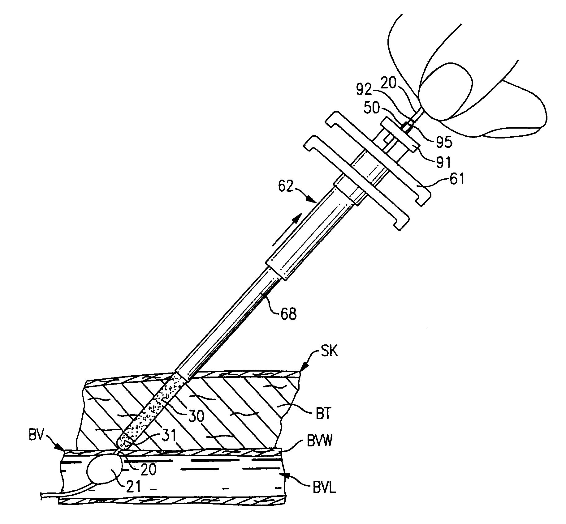
[0069]The first exemplary embodiment of the installation arrangement 12 is best seen in FIGS. 7-9. The installation arrangement 12 includes a delivery assembly 60 to carry the sealing material member 30 and separator member 31 and a plunger means 61 to hold the members 30 and 31 in a fixed position while the delivery assembly 60 is moved relative thereto.
[0070]The delivery assembly 60 seen in FIG. 7 includes a delivery tube 62 with a projecting leading end 64 thereon and with a pair of opposed gripping ears 65 at the opposite end thereof. The delivery tube 62 has an elongate tubular side wall 66 with central axis A4. The side wall is stepped intermediate its length so as to form a thinner puncture entering section 68 adjacent the leading end 64 and a thicker base section 69 at the trailing end of the side wall 66. The puncture entering section 68 has a length L4 greater than the greatest length of puncture PP likely to be encountered so that the base secti...
second exemplary embodiment
of Installation Arrangement
[0097]The second exemplary embodiment of the installation arrangement designated 112 is best seen in FIGS. 31-40. The installation arrangement 112 is designed to place a flowable sealing material 130 into the puncture PP and uses the separator member 31 to separate the flowable sealing material 130 from the blood vessel wall and the end of the puncture opening into the blood vessel lumen BVL. The installation arrangement 112 includes a sheath assembly 140 into which a delivery assembly 160 carrying the sealing material 130 and separator member 31 is slidably mounted, and a plunger means 161 to hold the material 130 and member 31 in a fixed position while the delivery assembly 160 is moved relative thereto and while the sheath assembly 140 is moved relative to the delivery assembly 160 as will become more apparent.
[0098]The sheath assembly 140 seen in FIG. 31 includes a sheath tube 141 with a projecting leading end 142 thereon and with a pair of opposed gri...
third exemplary embodiment
of Installation Arrangement
[0108]The third exemplary embodiment of the installation arrangement designated 212 is best seen in FIGS. 41-45. The installation arrangement 212 is also designed to place a flowable sealing material 230 into the puncture PP and uses the separator member 31 to separate the flowable sealing material 230 from the blood vessel wall and the end of the puncture opening into the blood vessel lumen BVL. The installation arrangement 212 includes a delivery assembly 260 carrying the sealing material 230 and separator member 31, and a plunger means 261 to hold the material 230 and member 31 in a fixed position while the delivery assembly 260 is moved relative thereto as will become more apparent.
[0109]The delivery assembly 260 seen in FIGS. 41 and 42 includes delivery tube 262 with a projecting leading end 264 thereon and with a pair of opposed gripping ears 265 at the opposite end thereof. The delivery tube 262 has an elongate tubular side wall 266 with central axi...
PUM
 Abstract
Description
Claims
Application Information
 - R&D
- Intellectual Property
- Life Sciences
- Materials
- Tech Scout
- Unparalleled Data Quality
- Higher Quality Content
- 60% Fewer Hallucinations
Browse by: Latest US Patents, China's latest patents, Technical Efficacy Thesaurus, Application Domain, Technology Topic, Popular Technical Reports.
© 2025 PatSnap. All rights reserved.Legal|Privacy policy|Modern Slavery Act Transparency Statement|Sitemap|About US| Contact US: help@patsnap.com


