
Video processing apparatus and a method of processing video data

a video processing apparatus and video data technology, applied in the field of video processing apparatus and a method of processing video data, can solve the problems of not being able to decode two adjacent i-macroblocks in a particular row in parallel, significant increase in the cost and complexity of the parser circuitry, and inability to fully decode content represented by one macroblock. , to achieve the effect of reducing the overall storage capacity, saving space in the buffer, and improving the performance of encoding

Active Publication Date: 2011-01-20
ARM LTD
View PDF4 Cites 25 Cited by
  • Summary
  • Abstract
  • Description
  • Claims
  • Application Information

AI Technical Summary

Benefits of technology

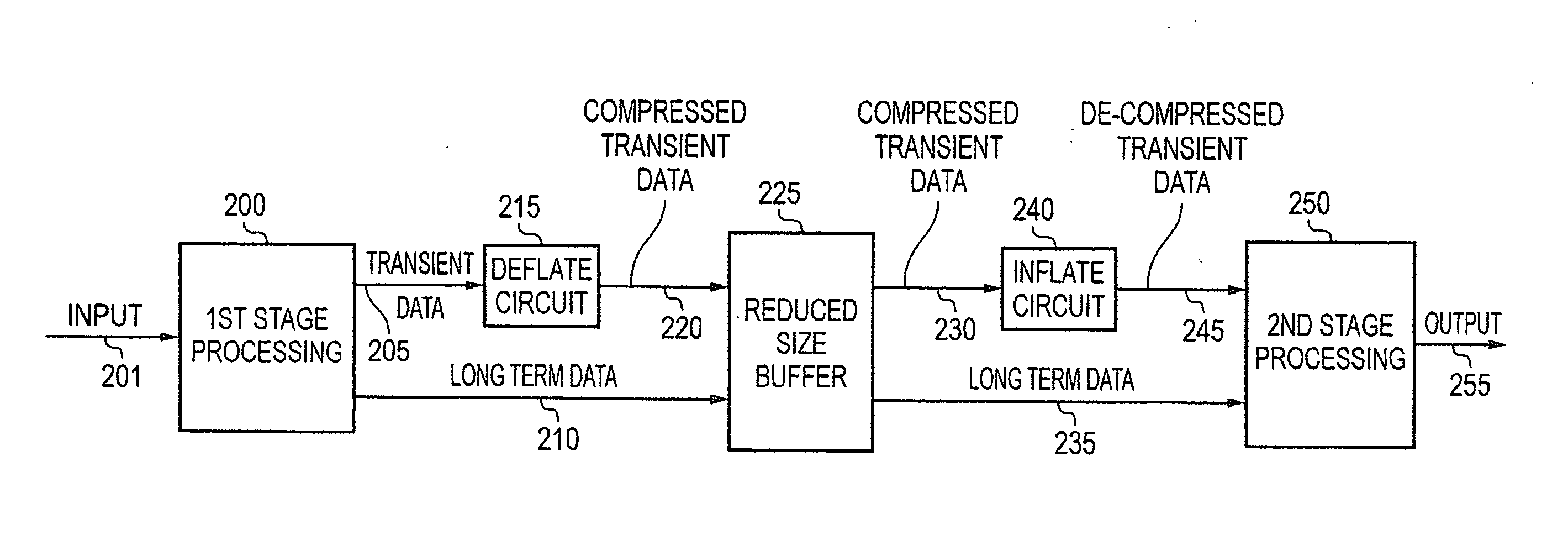
The present invention provides a video processing apparatus that separates video data into two types, namely transient data and long term data. This separation allows for efficient processing of video frames, as only the transient data needs to be stored in the buffer. The apparatus includes compression circuitry for compressing the transient data prior to storage, and decompression circuitry for decompressing the data prior to further processing. This approach reduces the amount of data that needs to be output for storing in the buffer, resulting in significant space savings. The invention also provides a method for processing video data in a video decoder or encoder.

Problems solved by technology

Further, there will be dependencies between various macroblocks, meaning that the content represented by one macroblock can only be fully decoded once one or more other macroblocks have been decoded.
Thus, if the parse stage is to be run in synchronisation with the pipe stage, then the parse circuitry needs to be able to cope in real time with the significant variation in complexity of the parsing operation on a macroblock by macroblock basis, leading to a significant increase in the cost and complexity of the parser circuitry.
For an I-macroblock, the macroblock immediately to the left needs to have been decoded before it is possible to fully decode the I-macroblock, and hence it would not be possible to decode two adjacent I-macroblocks in a particular row in parallel.
Further, for P-macroblocks, the decoding of these macroblocks involves the use of reference frame data when performing motion compensation, and often that reference frame data is locally cached.
However, as discussed in section 5.3, all of the data obtained by parsing the bitstream (i.e. the intermediate form referred to in FIG. 3) must be kept in a buffer until no longer required by the pipe circuitry, and this can lead to buffers of significant size due to the large amount of intermediate data that needs to be retained.
In particular, if the buffer is retained internally within the decode engine (i.e. the unit providing the parser circuitry and pipe circuitry), the size of the buffer required is likely to have a significant impact on the area and hence cost of the decoder.
If instead the buffer is provided externally to the decode engine, then this can give rise to significant bandwidth issues due to the need to write the intermediate data from the parser circuitry into the buffer and then to read that data from the buffer when subsequently required by the pipe circuitry.

Method used


Image

  • Video processing apparatus and a method of processing video data
  • Video processing apparatus and a method of processing video data
  • Video processing apparatus and a method of processing video data

Examples


Embodiment Construction

[0046]FIG. 4 is a block diagram illustrating a video processing apparatus in accordance with one embodiment. Input video data is received by the first stage video processing circuitry 200 over path 201. The first stage video processing circuitry then performs one or more processing operations on the input video data in order to generate an intermediate representation of the input video data. In accordance with the illustrated embodiment, this intermediate representation takes the form of two separate data portions, the first data portion containing transient data that is only required for processing a single video frame, the transient data being output over path 205, and the second data portion containing long term data required for processing of at least two video frames, the long term data being output over path 210.

[0047]As can be seen from FIG. 4, the long term data is passed to a buffer 225, but the transient data is first passed to a deflate circuit 215, where a compression op...


PUM


Abstract

A video processing apparatus and method are provided, the video processing apparatus comprising first stage video processing circuitry and second stage video processing circuitry. The first stage video processing circuitry receives input video data and performs one or more processing operations on the input video data to generate an intermediate representation of the input video data. The intermediate representation comprises first and second separate data portions, with the first data portion containing transient data derived from the input video data and the second data portion containing long term data derived from the input video data. Transient data is only required for processing of a single video frame, whilst the long term data is required for processing of at least two video frames. The first stage video processing circuitry is arranged to output the first and second separate data portions for storing in a buffer, and the second stage video processing circuitry then retrieves the first and second data portions from the buffer and performs one or more further processing operations on those data portions in order to generate output video data. The transient data is compressed prior to being stored in the buffer, and then decompressed when retrieved from the buffer by the second stage video processing circuitry. Such an approach enables the operations of the second stage video processing circuitry to be decoupled from the operations of the first stage video processing circuitry, whilst reducing the storage capacity requirements of the buffer.

Description

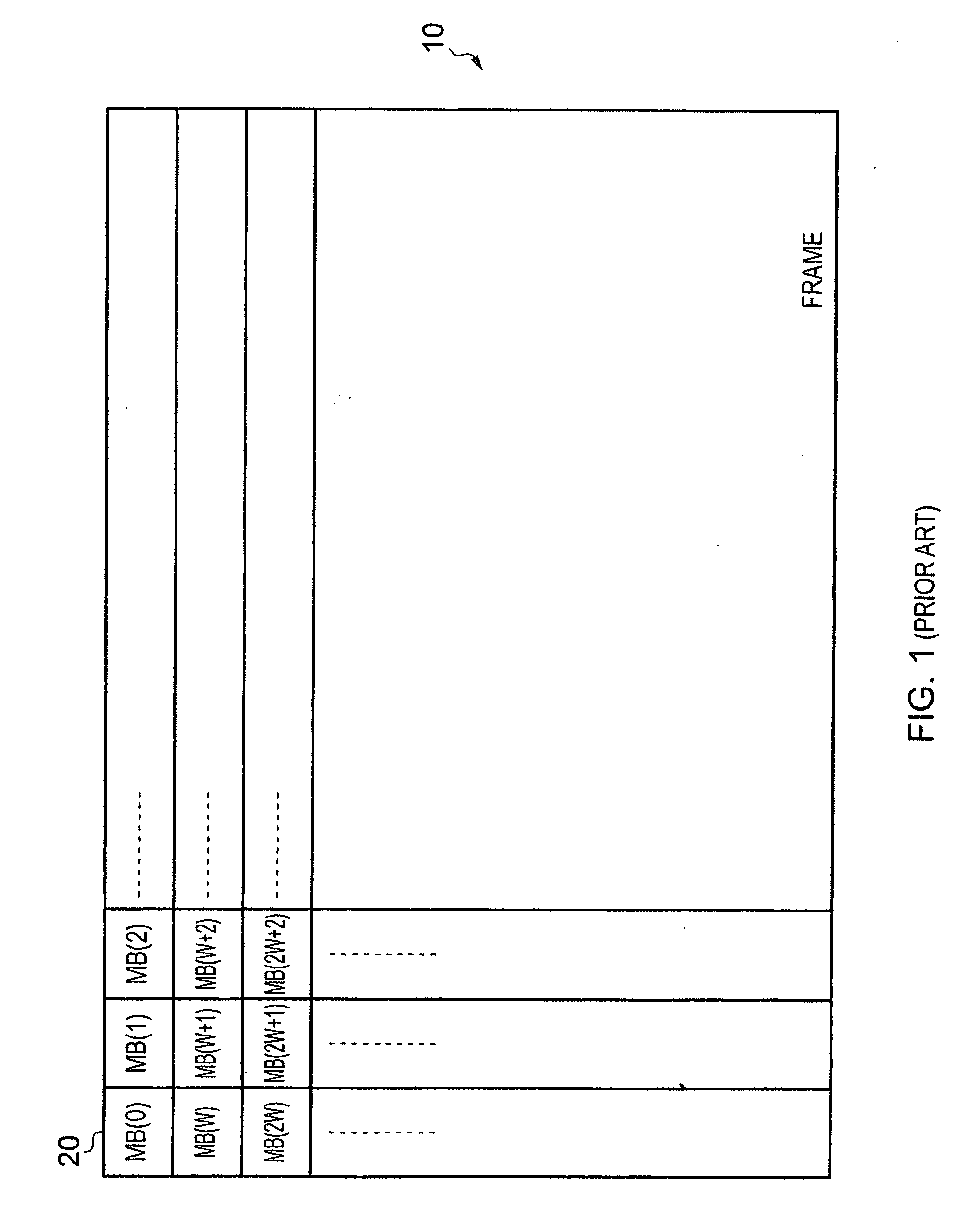
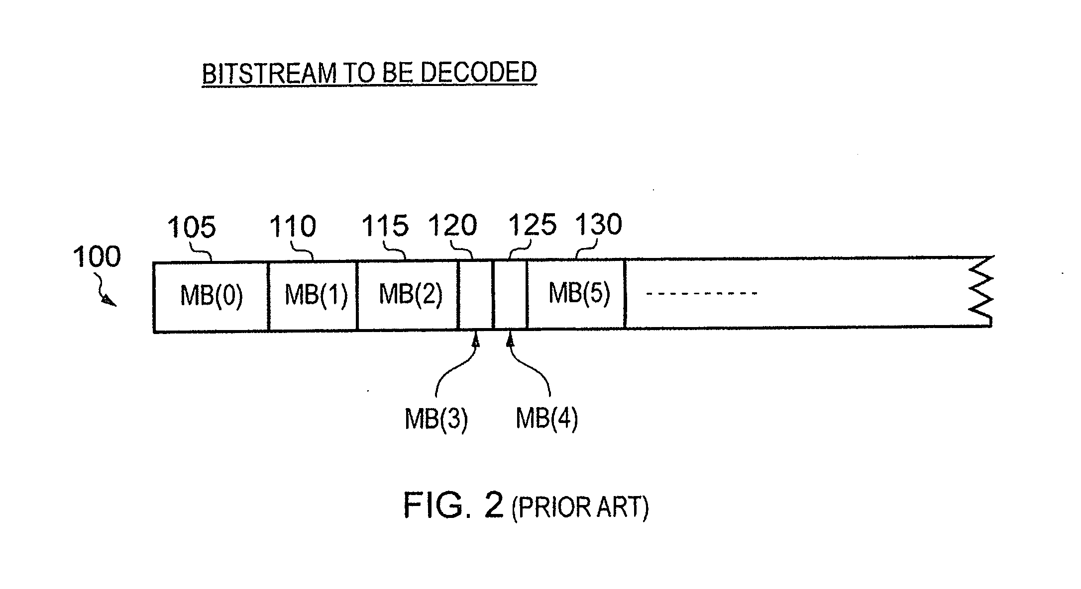
FIELD OF THE INVENTION[0001]The present invention relates to a video processing apparatus and a method of processing video data.BACKGROUND OF THE INVENTION[0002]Often video data is transmitted as an encoded bitstream, and accordingly an apparatus receiving that encoded bitstream will need to perform a decoding operation in order to derive the pixel data for each video frame of a video image encoded in that bitstream. As shown schematically in FIG. 1, each frame 10 can be considered to be formed of a series of macroblocks (MBs) 20 arranged in a series of rows and columns. Each macroblock represents a block of adjacent pixels, for example a rectangular 16×16 array of pixels. However, for the purposes of the present application, the term macroblock is not intended to imply any particular size of block, and accordingly larger or smaller arrays of pixels can be represented by each macroblock.[0003]The encoded bitstream will contain a sequence of macroblocks in encoded form, and each of t...

Claims


Application Information

Patent Timeline
Patent Type & Authority Applications(United States)
IPC IPC(8): H04N11/04H04N7/26H04N7/30
CPCH04N19/61H04N19/91H04N19/48H04N19/517H04N19/428H04N19/43H04N19/436H04N19/44H04N19/13H04N19/426
Inventor PERSSON, ERIKEDSO, TOMAS
Owner ARM LTD
Learn More