
Information reproduction apparatus and information reproduction method

Inactive Publication Date: 2011-01-20
RENESAS ELECTRONICS CORP
View PDF1 Cites 0 Cited by
  • Summary
  • Abstract
  • Description
  • Claims
  • Application Information

AI Technical Summary

Benefits of technology

[0026]The information reproduction apparatus and the information reproduction method according to the present invention, can select the most probable path in which the influence of a distortion is taken into account in response to the reproduction signal sequence, even when the reproduction signal includes a distortion. In particular, in the information reproduction apparatus and the information reproduction method according to the present invention, the error in the path determination can be reduced in a small circuit, and data can be stably reproduced without being influenced by the recording quality.

Problems solved by technology

However, in the PRML signal process, there is a case that the original performance of the PRML is not sufficiently provided because of the nonlinear distortion of the reproduction signal that is generated in association with the marks formed in high density.
However, the PRML signal process has a problem of drop in a detection performance when the nonlinear distortion is included in the reproduction signal, because deviation is generated in the path metric indicating the likelihood of a path.
However, there are limits in the change rates of a modulation pattern and an optical beam magnitude, and a deviation is apt to appear in the shape of a short mark.
This causes an increase of a detection error.
The increase in the circuit scale is not preferable because the electric power consumption and the cost are increased.
Thus, this has a demerit that, when the path determination is erroneous, it causes an increase in error in a subsequent path determination.
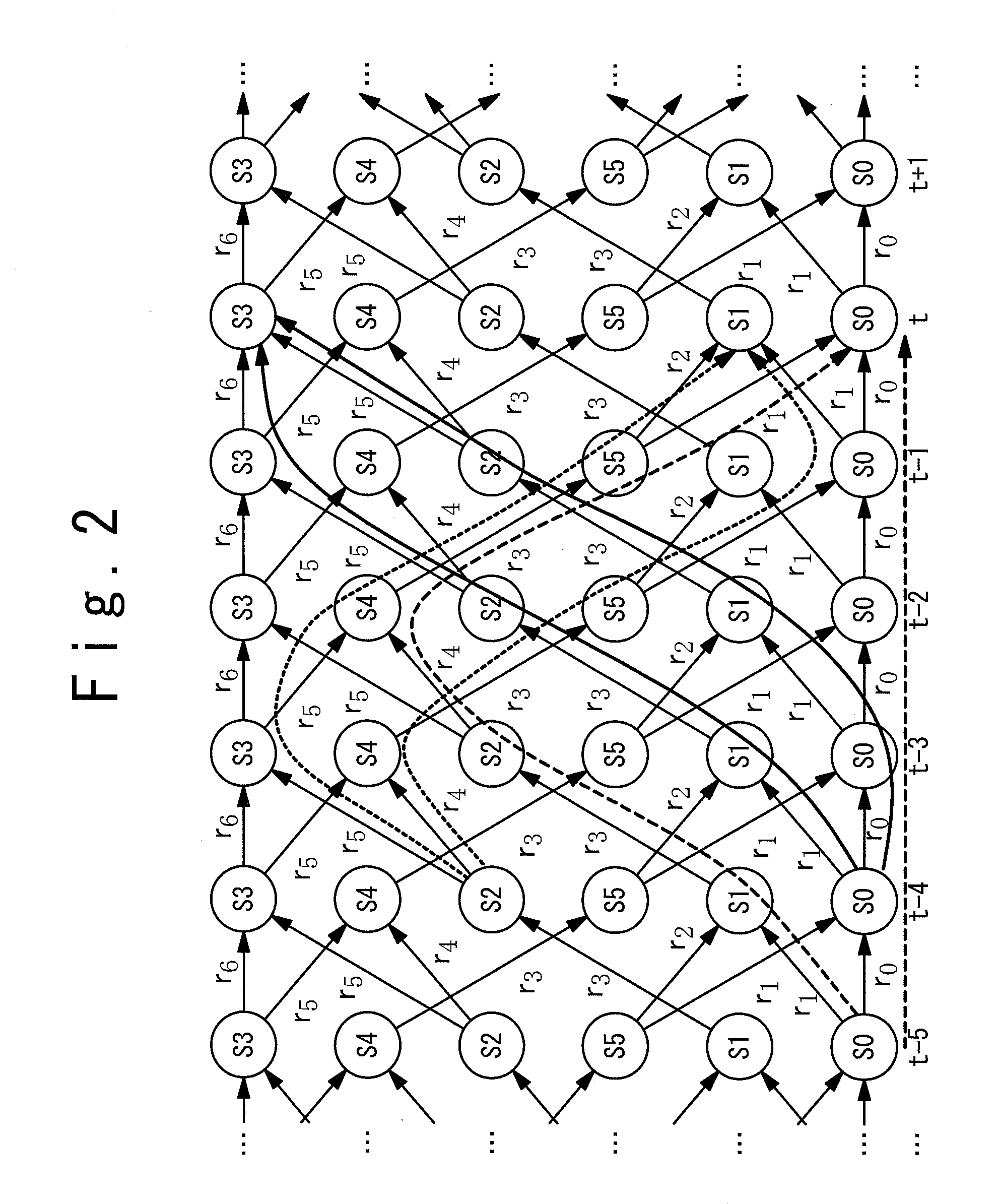
When the path selection at the time t is erroneous, the path metric P0[t] does not have a value reflecting the likelihood of the path, and there is a possibility that the determination error is continuously occurred.
Further, in a reproduction signal recorded in high density, the waveform distortion of the path in which the path metric difference between the ideal waveforms coincides with the minimum value mainly causes the increase in the error rate.
Those waveforms are reproduction signals obtained from short marks which are apt to generate a waveform distortion, and they are apt to cause an increase in the error rate.
However, the method indicated in the patent document 2 cannot correct the path metric between the two paths in which the Euclidean distance becomes the shortest.
For this reason, there is also a problem that the effect of improving the error rate cannot be obtained, in a reproduction signal recorded in high density.
Hence, an information reproduction apparatus and an information reproduction method are desired which can obtain a data determination result in which an error rate is low, in a small circuit scale, even if a nonlinear distortion is included in a reproduction signal.

Method used


Image

  • Information reproduction apparatus and information reproduction method
  • Information reproduction apparatus and information reproduction method
  • Information reproduction apparatus and information reproduction method

Examples


first embodiment

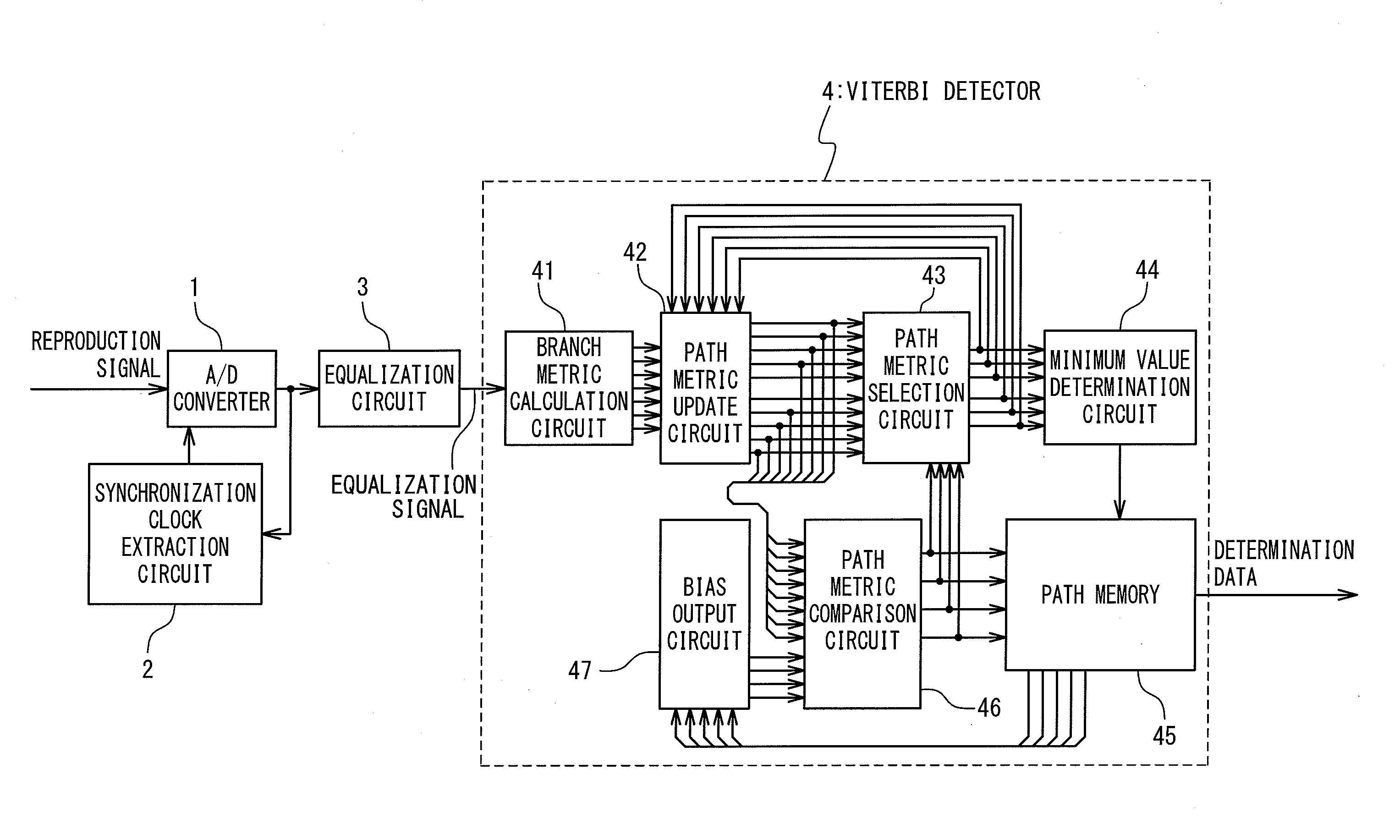
[0049]FIG. 4 is a block diagram of the information reproduction apparatus according to a first embodiment of the present invention. With reference to FIG. 4, the information reproduction apparatus contains an A / D converter 1, a synchronous clock extraction circuit 2, an equalization circuit 3 and a Viterbi detector 4.

[0050]The A / D converter 1 samples a reproduction signal in accordance with a sampling clock supplied by the synchronous clock extraction circuit 2. A digital data obtained by the sampling is fed back to the synchronous clock extraction circuit to keep an appropriate sampling timing corresponding to a data rate of the reproduction signal.

[0051]The equalization circuit 3 carries out a filtering in accordance with the sampled reproduction signal to output an equalization signal. The response characteristic of the equalization circuit 3 is predetermined corresponding to the reproduction signal so that the equalization signal is close to a desirable partial response waveform...

second embodiment

[0083]A second embodiment of the present invention will be described below. FIG. 10 is a block diagram of the information reproduction apparatus according to the second embodiment of the present invention. With reference to FIG. 10, the information reproduction apparatus contains an A / D converter 1, a synchronous clock extraction circuit 2, an equalization circuit 3 and a Viterbi detector 4. The operations of the A / D converter 1, the synchronous clock extraction circuit 2 and the equalization circuit 3 are similar to those of the first embodiment. Also, the Viterbi detector 4 is operated similarly to that of the first embodiment except that the bias output circuit 47 in FIG. 1 is replaced with a bias output circuit 48.

[0084]The bias output circuit 48 receives path information from the path memory 45 similarly to the bias output circuit 47. Moreover, the bias output circuit 48 receives: the path metric of the merging path from the path metric update circuit42; and the signal indicati...


PUM


Abstract

A small size circuit reproducing data with low error rate even when a signal includes a non-linear distortion is desired. In such a circuit, the Viterbi method is performed. In the Viterbi method, branch metrics are calculated based on a difference of a sampled reproduction signal and a predetermined expectation values. Path metrics are calculated from the branch metrics. Paths among the plurality of paths having the calculated path metrics and merging at a same state are compared with one another. Based on the magnitude of the compared path metrics, survivor path is selected. In the circuit, for the path metrics of paths merging at a same state, offset corresponding to a determination result until a merging point is added to the paths for the comparison for determining the survivor path from the plurality of merging paths.

Description

INCORPORATION BY REFERENCE[0001]This Patent Application is based on Japanese Patent Application No. 2009-166039. The disclosure of the Japanese Patent Application is incorporated herein by reference.BACKGROUND OF THE INVENTION[0002]1. Field of the Invention[0003]The present invention relates to an information reproduction apparatus and an information reproduction method, and more particularly relates to an information reproduction apparatus and an information reproduction method which can obtain a low determination error rate, even when a reproduction signal has a nonlinear distortion.[0004]2. Description of Related Art[0005]In recent years, the recording density of optical disc recording / reproducing apparatuses is increasing. In such apparatuses having high density, the PRML (Partial-Response Maximum-Likelihood) signal process is adopted in the signal reproduction process, in many cases. The PRML signal process carries out a waveform equalization corresponding to properties of the ...

Claims


Application Information

Patent Timeline
IPC IPC(8): G11B20/10
CPCG11B20/10009G11B20/10037G11B20/10055G11B20/10111G11B20/10462G11B20/10296G11B20/10351G11B20/10379G11B20/10277
Inventor KAYANUMA, KINJI
Owner RENESAS ELECTRONICS CORP
Learn More