
Transflective liquid crystal display

Inactive Publication Date: 2011-01-20
DONGGUAN MASSTOP LIQUID CRYSTAL DISPLAY +1
View PDF3 Cites 11 Cited by
  • Summary
  • Abstract
  • Description
  • Claims
  • Application Information

AI Technical Summary

Benefits of technology

One object of an embodiment of the invention is to provide a transflective liquid crystal display having reduced color washout observed at a large viewing angle. One object of another embodiment of the invention is to provide a transflective liquid crystal display having reduced fingerprint mura. One object of another embodiment of the invention is to provide a transflective liquid crystal display having fine image quality. One object of another embodiment of the invention is to provide a transflective liquid crystal display having optimum gamma curves for a transmissive area and a reflective area of the transflective liquid crystal display.
According to the above embodiments, a pixel has two distinct areas that are applied with mutually different electric fields, so that it is possible to slow down the speed of lighting for the reflective area that often becomes bright faster. Accordingly, the gamma curves for the transmissive and reflective areas are optimized to effectively reduce the color washout and fingerprint mura.

Problems solved by technology

Hence, it is not easy to adjust the gamma values for a transmissive area and a reflective area to approach a standard gamma curve 2.2, and therefore resulting in inferior image quality.

Method used


Image

  • Transflective liquid crystal display
  • Transflective liquid crystal display
  • Transflective liquid crystal display

Examples


Embodiment Construction

Note that, as used in the specification and the appended claims, the meaning of the phrase “layer A is formed or disposed on layer B” is not limited to a direct contact between the upper layer A and the lower layer B. For instance, in an embodiment where laminates are interposed between the upper layer A and the lower layer B is encompassed within the scope of the phrase “layer A is formed or disposed on layer B”.

FIG. 2 partially shows a schematic cross-section of a transflective liquid crystal display according to an embodiment of the invention. Referring to FIG. 2, the transflective liquid crystal display 10 includes a color filter substrate 12, an array substrate 14 and a liquid crystal layer 16. The color filter substrate 12 and the array substrate 14 are opposite each other. The liquid crystal layer 16 is interposed between the substrates 12 and 14 and has negative dielectric anisotropy, so that the liquid crystal molecules are in vertical alignment when a voltage is not applie...


PUM


Abstract

A transflective liquid crystal display is provided which includes a color-filter substrate, an active matrix substrate, and a liquid crystal layer interposed between them. The active matrix substrate includes a first transparent substrate and includes a plurality of switching devices, a plurality of transparent pixel electrodes and a plurality of reflective pixel electrodes formed on the first transparent substrate. The color-filter substrate includes a second transparent substrate, a first and second transparent conducting layers and a dielectric layer. The first transparent conducting layer is interposed between the second transparent substrate and the second transparent conducting layer, and the dielectric layer is interposed between the first and second transparent conducting layers. The second transparent conducting layer in each pixel area has at least one opening. The openings positionally correspond to the reflective pixel electrodes.

Description

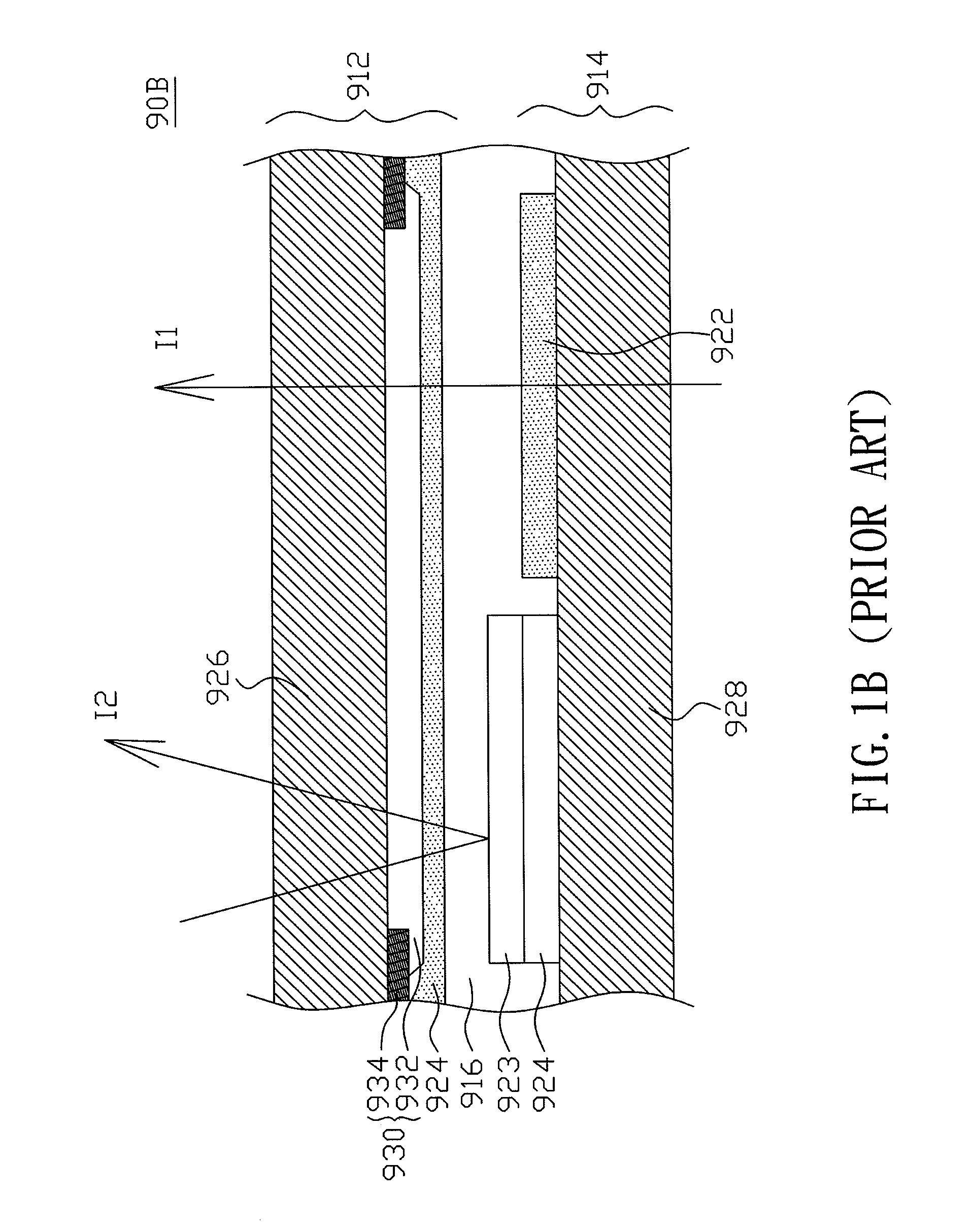
BACKGROUND OF THE INVENTION(a) Field of the InventionThe invention relates to a transflective liquid crystal display and, more particularly, relates to a transflective liquid crystal display having optimum gamma curves for a transmissive area and a reflective area of the transflective liquid crystal display.(b) Description of the Related ArtFIG. 1A partially shows a schematic cross-section of a conventional transflective liquid crystal display. Referring to FIG. 1A, the transflective liquid crystal display 90 includes a color filter substrate 912, an array substrate 914 and a liquid crystal layer 916. The color filter substrate 912 and the array substrate 914 are opposite each other. The liquid crystal layer 916 is interposed between the substrates 912 and 914 and has negative dielectric anisotropy, so that the liquid crystal molecules are in vertical alignment when a voltage is not applied thereto. Switching devices such as thin-film transistors (not shown), transparent pixel elect...

Claims


Application Information

Patent Timeline
IPC IPC(8): G02F1/1335
CPCG02F2001/134318G02F1/133555G02F1/134318
Inventor WANG, WEN-CHUNYU, MING-CHANGCHANG, YUNG-CHENG
Owner DONGGUAN MASSTOP LIQUID CRYSTAL DISPLAY
Learn More