Device and method for monitoring an escalator or moving walkway

Inactive Publication Date: 2011-01-20
KONE CORP
View PDF10 Cites 31 Cited by
  • Summary
  • Abstract
  • Description
  • Claims
  • Application Information

AI Technical Summary

Benefits of technology

[0011]This has the advantage that monitoring a checking function redundantly is crossed with the redundant monitoring in both directions of travel. The detector signals are compared to each other of detectors provided roughly in the same position or closely spaced from each other in producing roughly the same signal sequence. For example, the signals of the detectors are now arranged as a rule more in a defined spacing from the opposite ends of the comb plates of the escalator to realize the same checking function for both different directions of travel. The signals of these detectors, although identical in their pulse configuration, are phase-shifted.
[0055]In still another embodiment, at least one, for example two, handrail speed detectors may be provided in signal communication with the analyzer / controller electronics such as, e.g., by bus or wireless communication. In the same way at least one, for example two, motor speed detectors may be provided. The output of these detectors is in signal communication with the analyzer / controller electronics. This is how safe operation of the escalator as a function of the detectors for sensing handrail speed, motor speed and tread step monitoring can be enhanced, which because of the added sensor analysis complexity hitherto could not be integrated in safety chains formed as a rule by simple ON / OFF switches (e.g. door latch detectors).

Problems solved by technology

The hardware needed for this purpose is relatively complicated, especially when the system needs to be operated in both directions of travel.

Method used


Image

  • Device and method for monitoring an escalator or moving walkway
  • Device and method for monitoring an escalator or moving walkway
  • Device and method for monitoring an escalator or moving walkway

Examples


Embodiment Construction

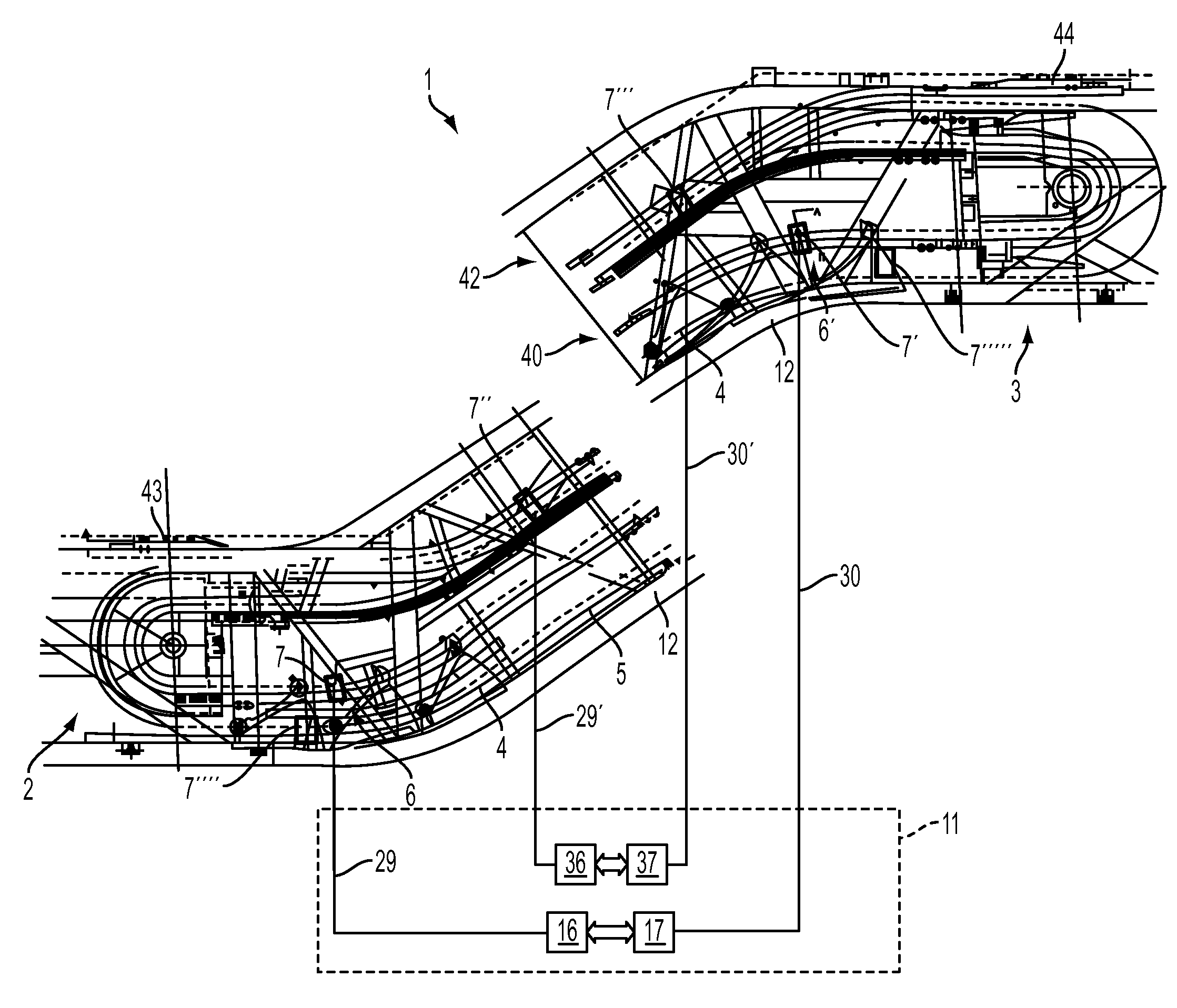
[0061]Referring now to the embodiment depicted in FIG. 1, there is illustrated an escalator 1 comprising two return portions 2, 3 for the steps 4 of the step belt 5. Arranged in the vicinity of the first return portion 2, and at a defined spacing away from the first comb plate 43, is a first detector 7. Likewise, in the vicinity of the second return portion 3, and at a defined spacing away from the second comb plate 44, is a second detector 7′. In this arrangement, the two detectors 7, 7′ are located as lower detectors in the return run 40, i.e. in the non-exposed portion of the escalator 1, so that no defect or missing step appears in the exposed portion. In the same way, in addition to or instead of the lower first and second detectors 7, 7′, upper first and second detectors 7″, 7′″ may be provided in the upper run 42, i.e. in the exposed portion of the escalator 1, to prevent a defective step from entering the exposed portion in the region of a comb plate 43, 44 where it could re...


PUM


Abstract

In an escalator or travelator configured to travel in two directions and including a step or pallet belt returned in first and second return portions facing away from each other, a monitoring device and method for detecting steps or pallets of the step or pallet belt is provided. The device includes a first detector configured to detect the steps or pallets in one of the directions of travel, a second detector configured to detect the steps or pallets in the other direction of travel, and an electronic analyzer / controller functionally coupled with each of the first and second detectors. The electronic analyzer / controller is configured to receive and compare signals from the first and second detectors for the two directions of travel and derive therefrom a signal for halting the escalator or travelator. When the signals from at least one of the first and second detectors indicates a missing step or pallet within the step or pallet belt, the electronic analyzer / controller outputs the derived signal to halt a drive of the escalator or travelator.

Description

CROSS-REFERENCE TO RELATED APPLICATION[0001]This application is a continuation application of International PCT Application No. PCT / EP2009 / 051658, filed Feb. 12, 2009, designating the United States and claiming priority of German Patent Application No. DE 102008009458.7, filed Feb. 15, 2008, the disclosure of both applications being incorporated by reference herein in their entireties.BACKGROUND OF THE INVENTION[0002]1. Field of Invention[0003]The invention relates to an escalator or travelator comprising a step or pallet monitoring device.[0004]2. Related Art[0005]Escalators and travelators must be equipped to meet existing safety codes in a number of countries around the world such that they automatically halt as soon as problems occur in some critical area.[0006]European patent document EP 1 289 871 discloses a device using a redundant method to safeguard the function of one or more detectors for detecting missing steps. The hardware needed for this purpose is relatively complica...

Claims


Application Information

Patent Timeline
IPC IPC(8): B66B29/00
CPCB66B29/005
Inventor PLATHIN, ANTTILANGE, DIRK
Owner KONE CORP
Why Eureka
Try Eureka