Eureka AIR delivers breakthrough ideas for toughest innovation challenges, trusted by R&D personnel around the world.

Enhanced surface cooling of thermal discharges

a technology of thermal discharge and surface cooling, which is applied in the direction of lighting and heating apparatus, ventilation systems, heating types, etc., can solve the problems of requiring the construction of extremely costly on-site cooling towers, and few, if any, existing u.s. facilities have been retrofitted with a full-scale cooling tower system, so as to facilitate surface cooling, increase heat transfer, and enhance heat transfer to the atmosphere

Inactive Publication Date: 2011-01-20
UNIV OF MASSACHUSETTS
View PDF7 Cites 3 Cited by
  • Summary
  • Abstract
  • Description
  • Claims
  • Application Information

AI Technical Summary

Benefits of technology

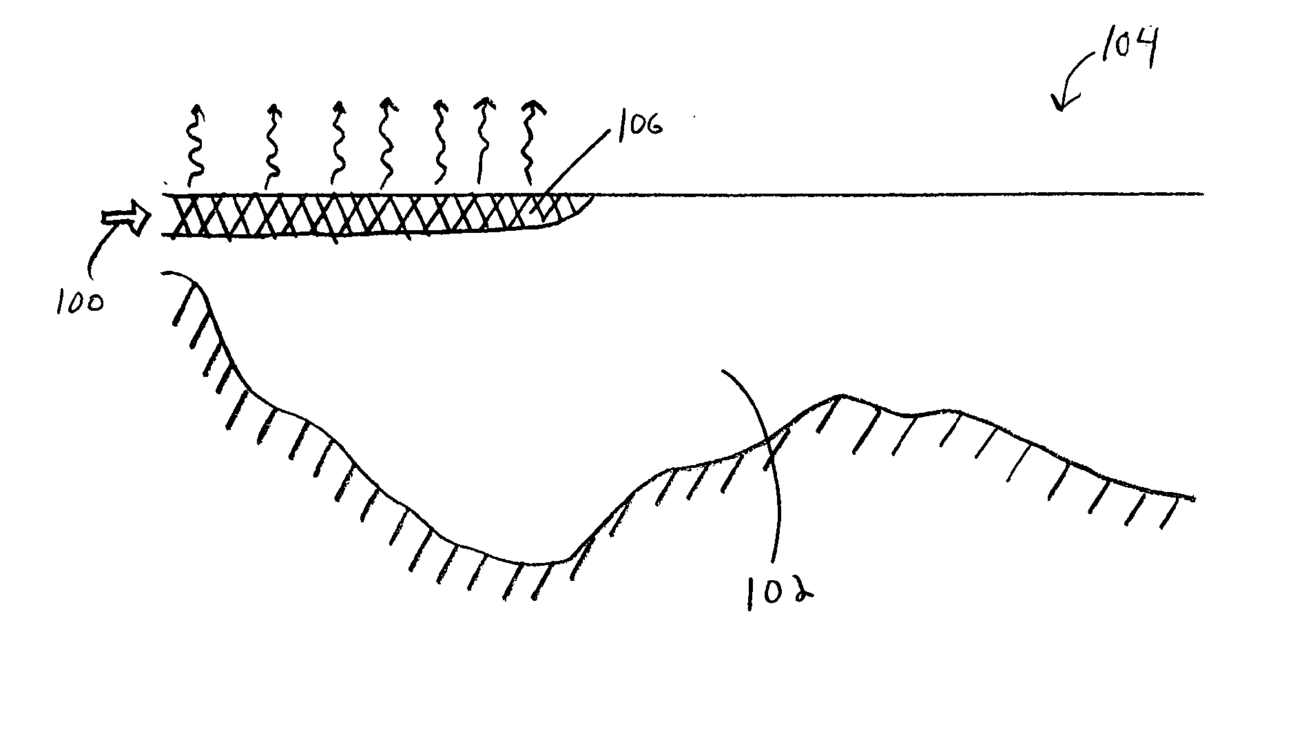
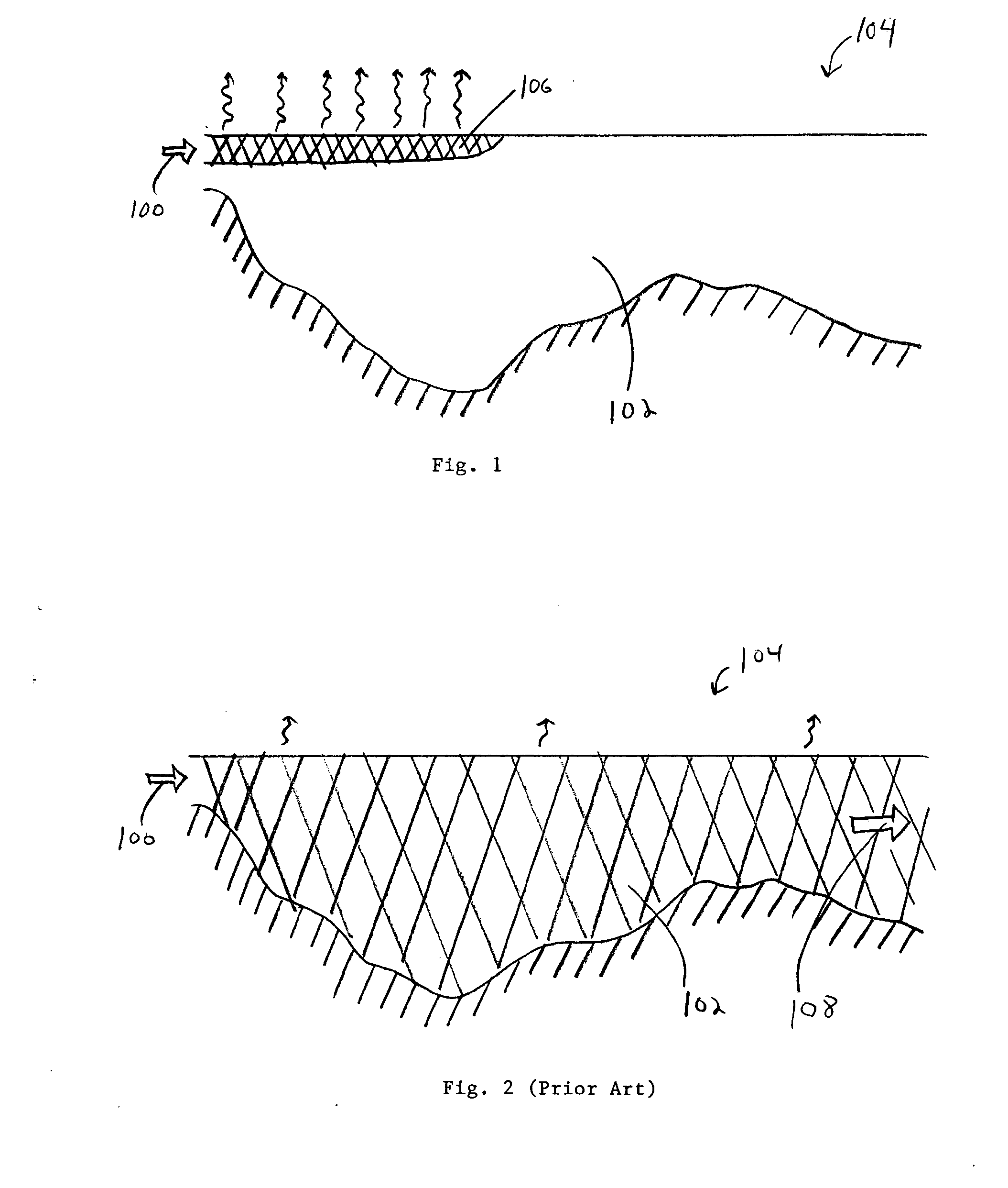
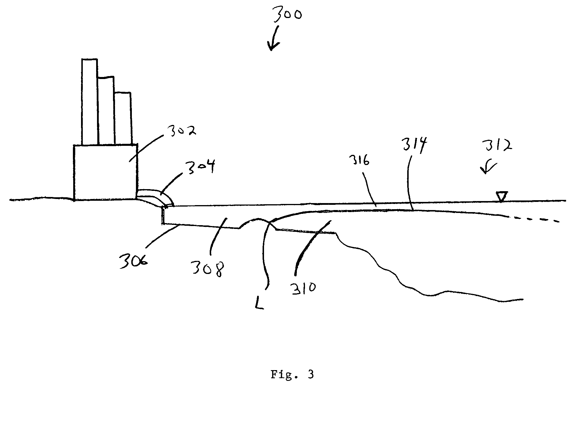
[0003]According to embodiments of the invention, a water discharge system is designed to enhance heat transfer to the atmosphere by limiting the mixing of heated discharge water with the ambient water of a receiving water body. The heated water is maintained near the top surface of the water body which increases the transfer of heat to the atmosphere as compared to a system where the discharge water is mixed quickly with the ambient water. Several embodiments of methods and systems which facilitate this surface cooling are disclosed herein, although other methods and systems may be used.

Problems solved by technology

Without clear scientific guidance upon which to rely, many regulatory entities, including the USEPA and state agencies, have chosen the conservative approach of mandating closed cycle cooling at locations where there is a potential for impact.
Closed cycle cooling involves the use of recycled cooling water, and requires the construction of extremely costly on-site cooling towers.
To date, few, if any, existing U.S. facilities have been retrofitted with a full scale cooling tower system, due primarily to high cost, which can be estimated to exceed $100 million in many cases.

Method used


Image

  • Enhanced surface cooling of thermal discharges
  • Enhanced surface cooling of thermal discharges
  • Enhanced surface cooling of thermal discharges

Examples


##ic example # 1

PROPHETIC EXAMPLE #1

[0066]First, we model a system that does not include aspects of the invention disclosed herein. Consider a discharge canal optimized for mixing with the following characteristics:[0067]Temperature difference between discharge and ambient water, ΔT=10° C.;[0068]Flow rate of discharge water, Q0=40 m3 / s;[0069]Depth of canal, h=4 m; and[0070]Width of canal, b=5 m

[0071]Given these initial values, the following values can be calculated from equations defined herein and from standard formulae:[0072]Velocity of discharge water, u=2 m / s;[0073]Excess heat flux discharged to receiving water body, Ho=1673 MW; and[0074]Reduced gravity, g′=0.025 m / s2.

[0075]to With the assumption that the entire plume exists within a bottom boundary layer, we calculate stress as τ=CDρu2, where CD=3×10⁻³. This yields a stress of 12 Pa. The shear production of turbulent kinetic energy, can be estimated as

P=τρ∂u∂z.

The amount of TKE converted to potential energy through mixing in a stratified envir...

##ic example # 2

PROPHETIC EXAMPLE #2

[0081]A modification to the system described in prophetic example #1 may be made by introducing a moving layer of ambient water underneath the discharge water to separate the shear region from the stratified region. In theory, this separation should shut down mixing completely due to values of Rig within the stratified region being much greater than ¼. However, production of unstratified turbulence within the shear layer will occur, which may be transported upward in the water column, eventually impacting the stratified region and resulting in mixing, however, a reduction in mixing on the order of approximately one order of magnitude is reasonable to assume. Thus, the atmospheric heat loss (1−H / Ho) in this prophetic example would be on the order of 36% of the total discharged excess heat load. This result is shown as point C in FIG. 12, corresponding to a value of

E=QoQ(1-HHo)=(0.5)(0.36)~0.2

Note that this heat loss is now of the order of the total dilution associ...


PUM


Abstract

A water discharge system enhances heat transfer to the atmosphere by limiting the mixing of heated discharge water with the ambient water of a receiving water body. The heated water is maintained near the top surface of the receiving water body which increases the transfer of heat to the atmosphere as compared to a system where the discharge water is mixed quickly with the ambient water.

Description

FIELD OF INVENTION[0001]The invention relates generally to cooling heated discharge water, and more specifically to improving the atmospheric cooling of heated water discharged to a receiving water body.DESCRIPTION OF RELATED ART[0002]The prevailing wisdom in the design and construction of outfalls often can be summed up by the adage “the solution to pollution is dilution”. Outfalls are typically designed to mix the discharging effluent into background waters as efficiently and quickly as possible, in order to reduce contaminant concentrations and / or water temperatures. This mixing is typically accomplished by using high fluid velocities at the outfall created by narrow discharge channels, or by using specially designed nozzles associated with offshore bottom diffusers connected to a shore-based industry or treatment facility via subsurface piping. The textbook, Mixing in Inland and Coastal Waters (Fischer et al., 1979) addresses design issues related to maximal mixing. The United S...

Claims


Application Information

Patent Timeline
Patent Type & Authority Applications(United States)
IPC IPC(8): F24J3/00F24F7/00
CPCE02B1/003
Inventor MACDONALD, DANIEL G.
Owner UNIV OF MASSACHUSETTS
Why Eureka
Eureka Blog
Learn More