
Defrost system and method for a subcritical cascade R-744 refrigeration system

a refrigeration system and subcritical cascade technology, applied in the field of refrigeration defrost system, can solve the problems of affecting the use of many conventional refrigerants containing or releasing cfc (chlorofluorocarbon) base chemicals, the accumulation of frozen water on the evaporator, and the air defrost system and method techniques, so as to achieve less space, less energy, and relatively quick defrost

Active Publication Date: 2011-01-20
SYST LMP INC +1
View PDF15 Cites 13 Cited by
  • Summary
  • Abstract
  • Description
  • Claims
  • Application Information

AI Technical Summary

Benefits of technology

"The present invention provides an improved defrost system and method for a subcritical cascade refrigeration system that uses less space, energy, and time than existing systems. The defrost system uses a defrost inlet heat exchanger and defrost compressor to circulate condensed refrigerant from the high stage condenser to the high stage heat exchanger and evaporators during a refrigeration cycle. This ensures that the evaporators are defrosted quickly and efficiently. The system also uses less energy and space than traditional air defrost systems, making it more energy-efficient and space-saving."

Problems solved by technology

However, due to environmental concerns, use of many conventional refrigerants containing or releasing CFC (chlorofluorocarbon) base chemicals is becoming less desirable.
Unfortunately, as with all refrigeration systems, the temperature of the evaporators must be maintained near or slightly below freezing to cool the load to desired temperature, which causes an accumulation of frozen water on the evaporators, and notably the low stage evaporators in cascade systems.
Unfortunately, air defrost systems and methods techniques, in which ambient or slightly heated air is blown by fans over the evaporators to melt the ice, are slow and require a great deal of space.
Electrical defrost systems and methods, in which heating coils or heaters are deployed in proximity to or on the evaporators, require less time to defrost but use large amounts of electricity.

Method used


Image

  • Defrost system and method for a subcritical cascade R-744 refrigeration system
  • Defrost system and method for a subcritical cascade R-744 refrigeration system

Examples


Embodiment Construction

[0031]With reference to the annexed drawings the preferred embodiments of the present invention will be herein described for indicative purpose and by no means as of limitation.

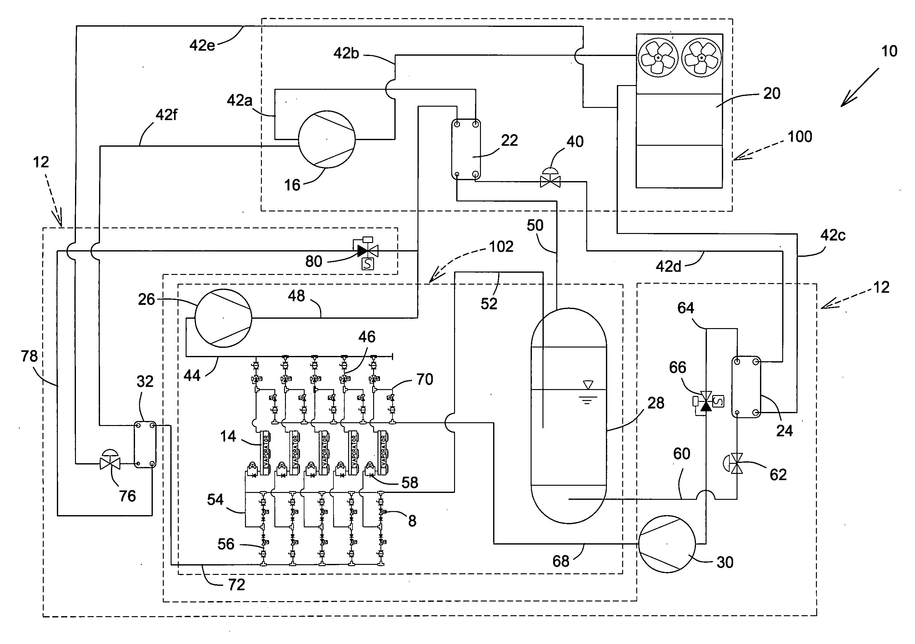
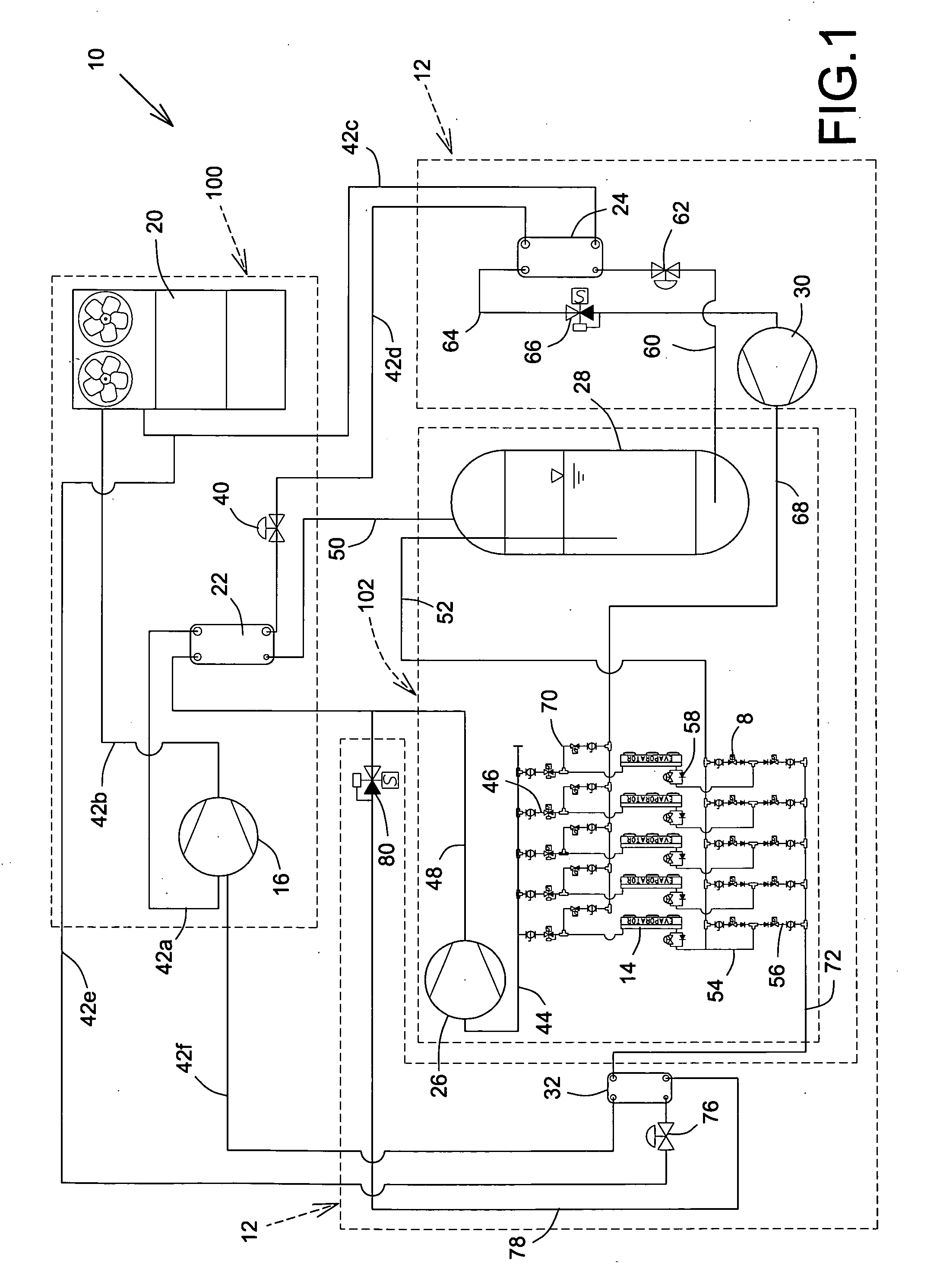
[0032]Referring to FIG. 1, there is schematically shown a subcritical cascade R-744 refrigeration system, shown generally as 10, having a reverse cycle gas defrost system or subsystem, shown generally as 12, a high stage refrigeration system or subsystem, shown generally as 100, and a low stage refrigeration subsystem or system, shown generally as 102. For the refrigeration system 10, a first, high stage, refrigerant is compressed, condensed, and then evaporated in the high stage 100 to condense a second, low stage R-744 refrigerant which is used to cool a thermal load in the low stage system 102. The first refrigerant may be any suitable refrigerant conventionally used in the high stage of cascade refrigeration systems, for example ammonia, Freon®, or the like. The second refrigerant is R-744, i.e. carbon di...


PUM


Abstract

A cascade refrigeration system using a first refrigerant or a high stage and a second, R-744, refrigerant for low stage refrigeration has a defrost system including a defrost compressor, a defrost inlet heat exchanger and defrost outlet heat exchanger. The defrost inlet heat exchanger receives a defrost portion of second refrigerant and adds an additional defrost heat load thereto from first refrigerant, thus evaporating defrost portion. Defrost portion is then compressed into high pressure defrost vapor potion in the defrost compressor. The defrost vapor portion is then circulated through a selected evaporator, where a defrost heat, augmented by additional defrost heat load, defrosts selected evaporator, defrost vapor being at least partially condensed into defrost condensed portion which is liquefied in defrost outlet heat exchanger.

Description

CROSS-REFERENCE TO RELATED APPLICATION[0001]The present invention has been previously described in U.S. provisional patent application No. 61 / 213,836 filed on Jul. 20, 2009, of which priority benefit is claimed and which is incorporated herein by reference.FIELD OF THE INVENTION[0002]The present invention relates to defrost systems for refrigeration, and is more particularly directed to defrost system for a subcritical cascade R-744 refrigeration system.BACKGROUND OF THE INVENTION[0003]Cascade refrigeration systems are well known in the art. In such systems, a first refrigerant of a high stage system is compressed in a high stage compressor, condensed in a high stage condenser, and used, in a high stage evaporator, to condense a second refrigerant compressed by a low stage compressor and then evaporated in a low stage evaporator by absorption of heat from a thermal load, thereby cooling the load. Thus, the high stage system, and notably the high stage heat exchanger, is used as a co...

Claims


Application Information

Patent Timeline
Patent Type & Authority Applications(United States)
IPC IPC(8): F25D21/06F25B1/10F25D17/02F25B39/04
CPCF25B5/02F25B7/00F25B9/008F25B2400/16F25B2309/06F25B2347/021F25B47/022
Inventor LESAGE, GAETANKANTCHEV, JORDAN
Owner SYST LMP INC
Learn More