
Resource sharing between a plurality of communication networks

Active Publication Date: 2011-01-06
MOTOROLA SOLUTIONS INC
View PDF14 Cites 12 Cited by
  • Summary
  • Abstract
  • Description
  • Claims
  • Application Information

AI Technical Summary

Benefits of technology

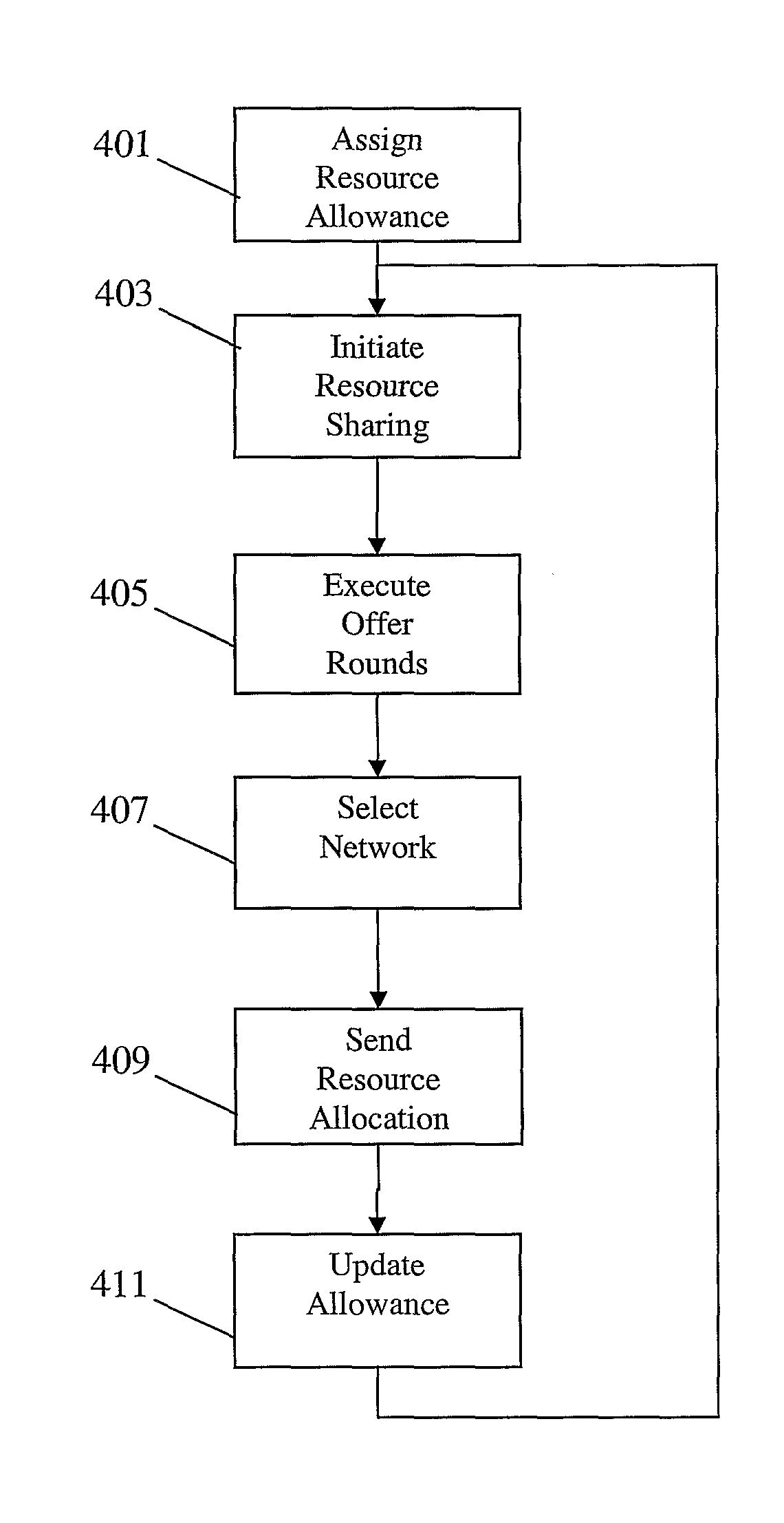
[0008]The invention may allow improved resource sharing between different networks. An efficient management of resource sharing may be achieved. All or some of the nominal resource allocation for one network may temporarily be reassigned to another network (or to a plurality of other networks) without necessitating a complex and / or combined resource allocation. The invention may e.g. allow a temporary resource re-allocation to the network requiring it most through a simple offer mechanism. An efficient dynamic resource sharing is enabled while maintaining the required interworking and coordination between the communication networks. In particular, the iterative nature of the offer rounds allow for an improved resource sharing and distribution to networks most in need of the resource.
[0048]This may provide for a simple sharing of resource which may provide efficient performance and which typically may reduce the impact of the sharing of resource on the first network and / or the second network. The frequency band may be a contiguous or fragmented frequency band.

Problems solved by technology

However, a static allocation of resource to different networks will typically not result in an optimal utilisation of the available resource as the resource requirements for individual networks tend to vary dynamically.
However, current approaches for dynamic allocation of a shared air interface resource to individual networks tend to be complex, result in suboptimal resource sharing and suboptimal performance for the individual networks.

Method used


Image

  • Resource sharing between a plurality of communication networks
  • Resource sharing between a plurality of communication networks
  • Resource sharing between a plurality of communication networks

Examples


Embodiment Construction

[0075]The following description focuses on embodiments of the invention applicable to broadband Wireless Metropolitan Area Networks (WMAN) such as the IEEE 802.16, and Wireless Local Area Networks (WLANs) communication networks such as 802.11 but it will be appreciated that the invention is not limited to this application but may be applied to many other communication networks such as for example GSM (Global System for Mobile communication) or UMTS (Universal Mobile Telecommunication System) cellular communication systems.

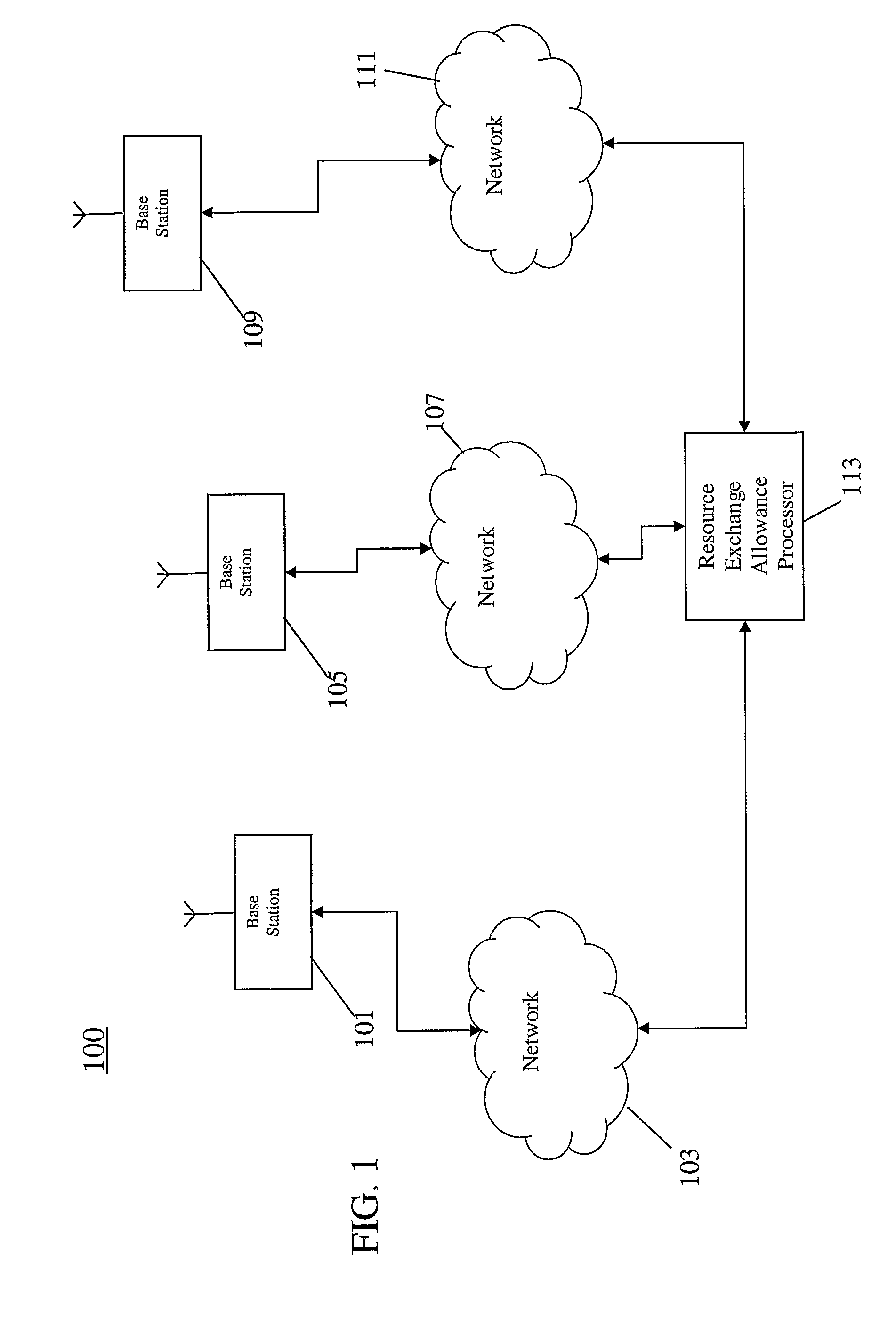
[0076]FIG. 1 illustrates an example of a combined communication system arrangement comprising three different individual broadband Wireless Metropolitan Area Networks (WMAN) 103, 107, 111.

[0077]Each of the networks 103, 107, 111 comprises all the required functionality for supporting communication services in accordance with the Technical Specifications of the WMAN system. In the specific example, the networks 103, 107, 111 comprise functionality for supporting com...


PUM


Abstract

A method of resource sharing between a plurality of communication networks each having a nominal resource allocation of a shared air interface resource and a resource exchange allowance is provided. A temporary resource allocation of a first air interface resource from a nominal resource allocation of a first network is initiated (403). Subsequently, a plurality of offer rounds are executed (405) with each offer round comprising determining offer values for the first air interface resource. A second network is then selected (407) in response to the determined offer values and subsequently a resource allocation message is transmitted (409) to the second network. The resource allocation message indicates a temporary allocation of at least part of the first air interface resource from the first network to the second network. Consequently, the resource exchange allowance of the second network is reduced (411) accordingly. Each offer round comprises receiving new offer values from the first plurality of networks.

Description

FIELD OF THE INVENTION[0001]The invention relates to resource sharing between a plurality of communication networks and in particular, but not exclusively, to temporary air interface resource re-allocation between broadband Wireless Metropolitan Area Networks (WMAN).BACKGROUND OF THE INVENTION[0002]In the last decades, wireless communication systems have become ubiquitous. For example, cellular communication systems, broadband Wireless Metropolitan Area Networks (WMAN) and wireless Local Area Networks (WLANs) have become widespread as a means to provide efficient communication services to e.g. mobile communication units. However, the increased prevalence of wireless communication systems have resulted in a dramatically increased need for air interface resources and the need for efficiently and flexibly utilising the available resource has become essential for the further development of wireless systems.[0003]A method that has been proposed for effectively increasing the utilisation ...

Claims


Application Information

Patent Timeline
IPC IPC(8): H04W72/04G06F15/16H04W16/14
CPCH04W16/14H04W28/0205
Inventor GRANDBLAISE, DAVIDDUNAT, JEAN-CHRISTOPHEPINTENET, REMY
Owner MOTOROLA SOLUTIONS INC
Learn More