Kneading extruder

a technology of extruder and kneading screw, which is applied in the direction of liquid based dampers, rotary stirring mixers, mixers, etc., can solve the problems of increasing the risk of breaking the shaft or the speed regulator of the kneading screw, and the speed regulator cannot be constant, so as to prevent the risk of breaking

Inactive Publication Date: 2011-01-06
KOBE STEEL LTD
View PDF14 Cites 2 Cited by
  • Summary
  • Abstract
  • Description
  • Claims
  • Application Information

AI Technical Summary

Benefits of technology

[0009]It is another object of the invention to provide a kneading extruder which makes it possible to prevent breakage due to resonance regardless of the value of kneading screw rotating speed.
[0010]In one aspect of the invention, a kneading extruder comprises a driving motor, a kneading screw for kneading a material, the kneading screw having a shaft, a motive power transmitting path including a first speed regulator for varying a rotating speed produced by motive power output from the driving motor, the motive power transmitting path serving to transmit the motive power which produces a rotating speed varied by the first speed regulator to the shaft of the kneading screw, and a resonance suppressor for suppressing torsional resonance of the kneading screw caused by fluctuations in load exerted on the kneading screw, the resonance suppressor serving to reduce a resonance response factor which is the ratio of an output amplitude of the kneading screw amplified by resonance response to an input amplitude of the kneading screw caused by the fluctuations in load to suppress the torsional resonance.

Problems solved by technology

Therefore, if the frequency of the load happens to coincide with the natural frequency of torsional motion of a rotary shaft system made up of the screws of the twin-screw kneading extruder and a shaft of the speed regulator, resonance can occur, causing an increased risk of breakage of kneading screw shafts or the speed regulator.
Inverter-driven, variable-speed-type twin-screw kneading extruders increasingly used in recent years, however, do not operate at a constant kneading screw rotating speed.
Therefore, even if the natural frequency of the twin-screw kneading extruder is varied, there is still a high risk of the occurrence of resonance depending on operating conditions and it has not been possible to prevent the occurrence of resonance in a reliable fashion.

Method used


Image

  • Kneading extruder
  • Kneading extruder
  • Kneading extruder

Examples


first embodiment

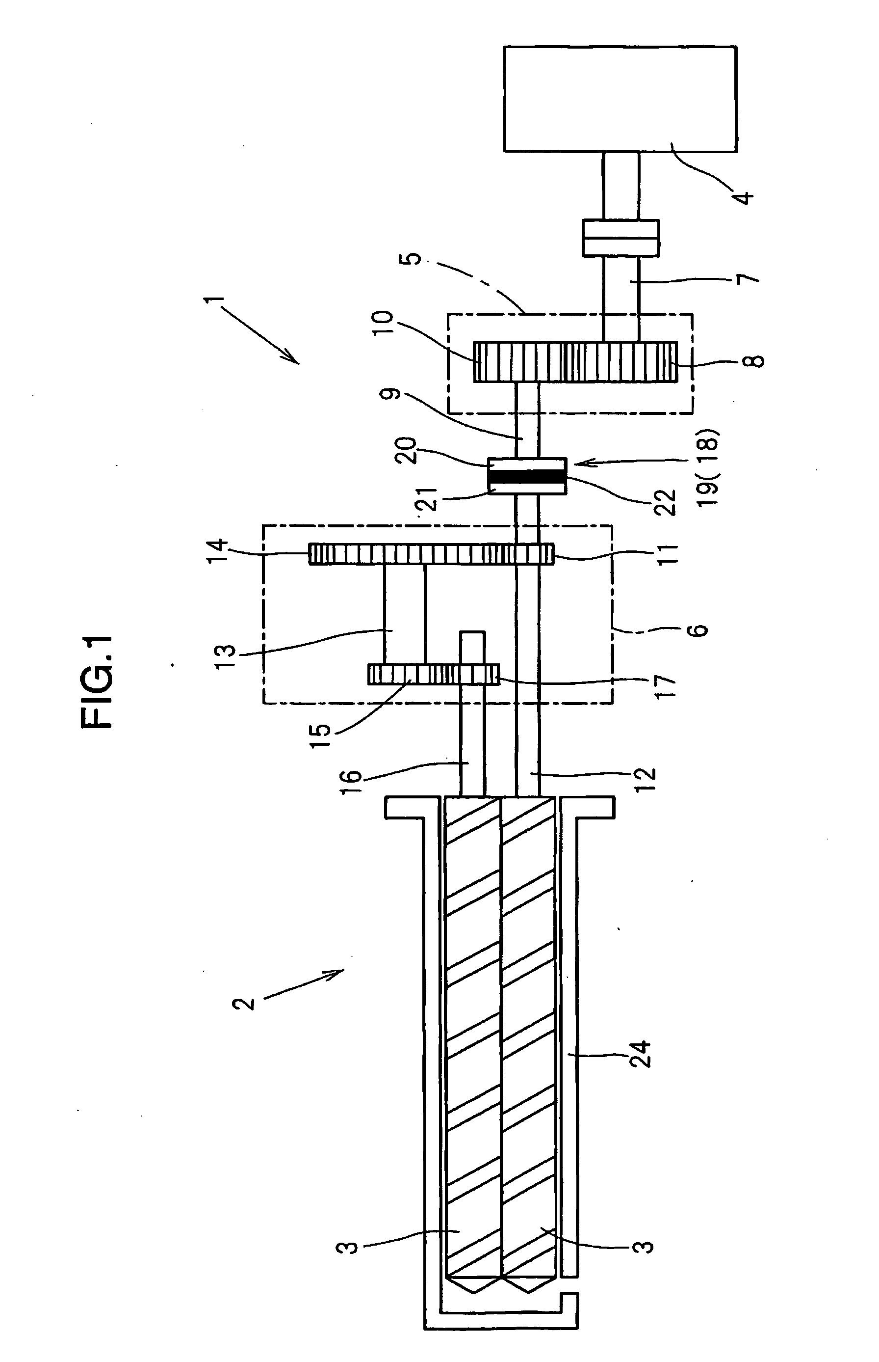
[0023]A first embodiment of the present invention is now described with reference to the drawings.

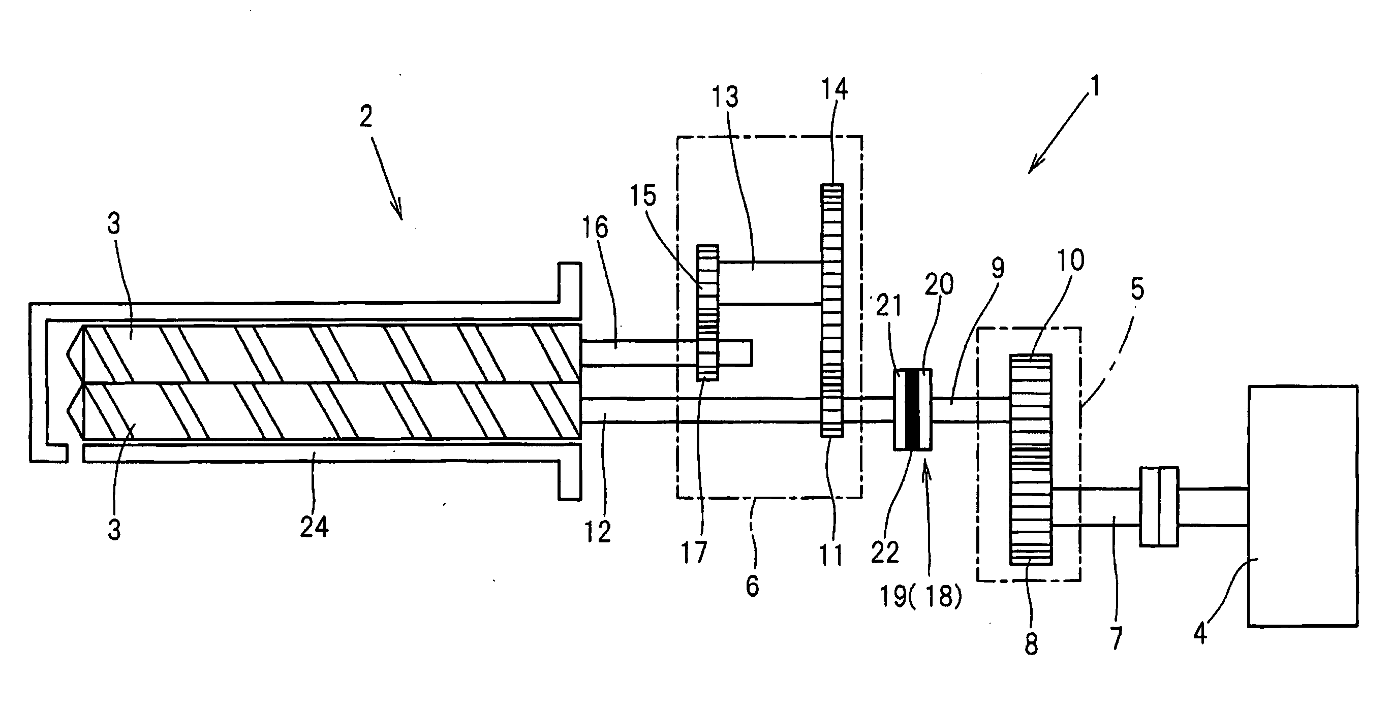
[0024]As schematically shown in FIG. 1, a twin-screw kneading extruder 2 of the first embodiment is of a co-rotation intermeshing type. The twin-screw kneading extruder 2 comprises a barrel 24 having a cavity inside, a pair of kneading screws 3 fitted within the barrel 24 and a motive power generation / transmission mechanism 1 for driving the kneading screws 3 to rotate.

[0025]In the following discussion, a left side as depicted in FIG. 1 is referred to as a downstream side of the twin-screw kneading extruder 2 and a right side as depicted in FIG. 1 is referred to as an upstream side thereof. Also, a left / right direction as depicted in FIG. 1 is referred to as an axial direction of the twin-screw kneading extruder 2.

[0026]The twin-screw kneading extruder 2 is configured such that a rotational driving force (motive power) produced by the motive power generation / transmission mechanism 1 is ...

second embodiment

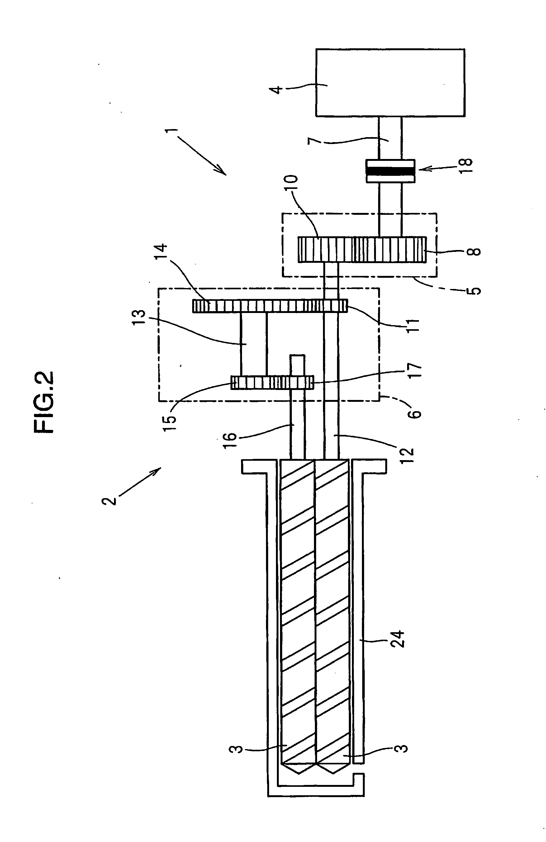
[0047]Next, a twin-screw kneading extruder 2 provided with a motive power generation / transmission mechanism 1 according to a second embodiment is described.

[0048]As shown in FIGS. 6 to 11, the twin-screw kneading extruder 2 of the second embodiment differs from that of the first embodiment in the configuration of the motive power generation / transmission mechanism 1. The motive power generation / transmission mechanism 1 of the second embodiment differs from that of the first embodiment in that a pair of screw shafts 12, 16 is provided with a resonance suppressor 18 differing from that of the first embodiment. It is to be noted that the configuration and operational and working effects of the motive power generation / transmission mechanism 1 of the second embodiment are otherwise the same as those of the first embodiment.

[0049]The resonance suppressor 18 provided in the motive power generation / transmission mechanism 1 of the second embodiment is made up of a phase difference damper 29 f...


PUM

PropertyMeasurementUnit
speedaaaaaaaaaa
moment of inertiaaaaaaaaaaa
phaseaaaaaaaaaa

Abstract

It is intended to provide a kneading extruder which makes it possible to prevent breakage due to resonance regardless of the rotating speed of kneading screws. The kneading extruder comprises a driving motor, kneading screws for kneading a material, each of the kneading screws having a screw shaft, a motive power transmitting path including a first speed regulator for varying a rotating speed produced by motive power output from the driving motor, the motive power transmitting path serving to transmit the motive power which produces a rotating speed varied by the first speed regulator to the screw shafts of the kneading screws, and a resonance suppressor for suppressing torsional resonance of the kneading screws caused by fluctuations in load exerted on the kneading screws, the resonance suppressor serving to reduce a resonance response factor which is the ratio of an output amplitude of the kneading screw amplified by resonance response to an input amplitude of the kneading screw caused by the fluctuations in load to suppress the torsional resonance.

Description

TECHNICAL FIELD[0001]The present invention relates to a kneading extruder.BACKGROUND ART[0002]Generally, in a twin-screw kneading extruder, composite resin material like a plastic compound is manufactured by feeding macromolecular resin pellets constituting base material and a powdered additive into a barrel and transferring the pellets and the additive downstream while kneading the same by means of a pair of kneading screws passed through the barrel. This kind of twin-screw kneading extruder employs a mechanism in which motive power of a driving motor is divided into two parts by a speed regulator and the divided parts of the motive power are transmitted to the individual kneading screws.[0003]Rotational resistance exerted on the kneading screws when the kneading screws are rotated is not constant. Since this rotational resistance varies with a kneaded material type, the number of fins formed on each kneading screw and rotating speed thereof, fluctuations in load occur in the knead...

Claims


Application Information

Patent Timeline
Patent Type & Authority Applications(United States)
IPC IPC(8): B01F7/00B29C48/40B29C48/405B29C48/57
CPCB29B7/46B29C47/6056F16F9/30F16F9/12B29C48/57B29C48/405B29C48/40
Inventor HONKE, KOICHIMINAGAWA, KOJI
Owner KOBE STEEL LTD
Why Eureka
Try Eureka