
Voltage regulator

a voltage regulator and voltage regulator technology, applied in the direction of electric variable regulation, process and machine control, instruments, etc., can solve the problems of large or potentially infinite transient response time, unstable feedback loop of the regulator that controls the current source, and improper circuit operation

Active Publication Date: 2011-01-06
STMICROELECTRONICS INT NV
View PDF5 Cites 21 Cited by
  • Summary
  • Abstract
  • Description
  • Claims
  • Application Information

AI Technical Summary

Benefits of technology

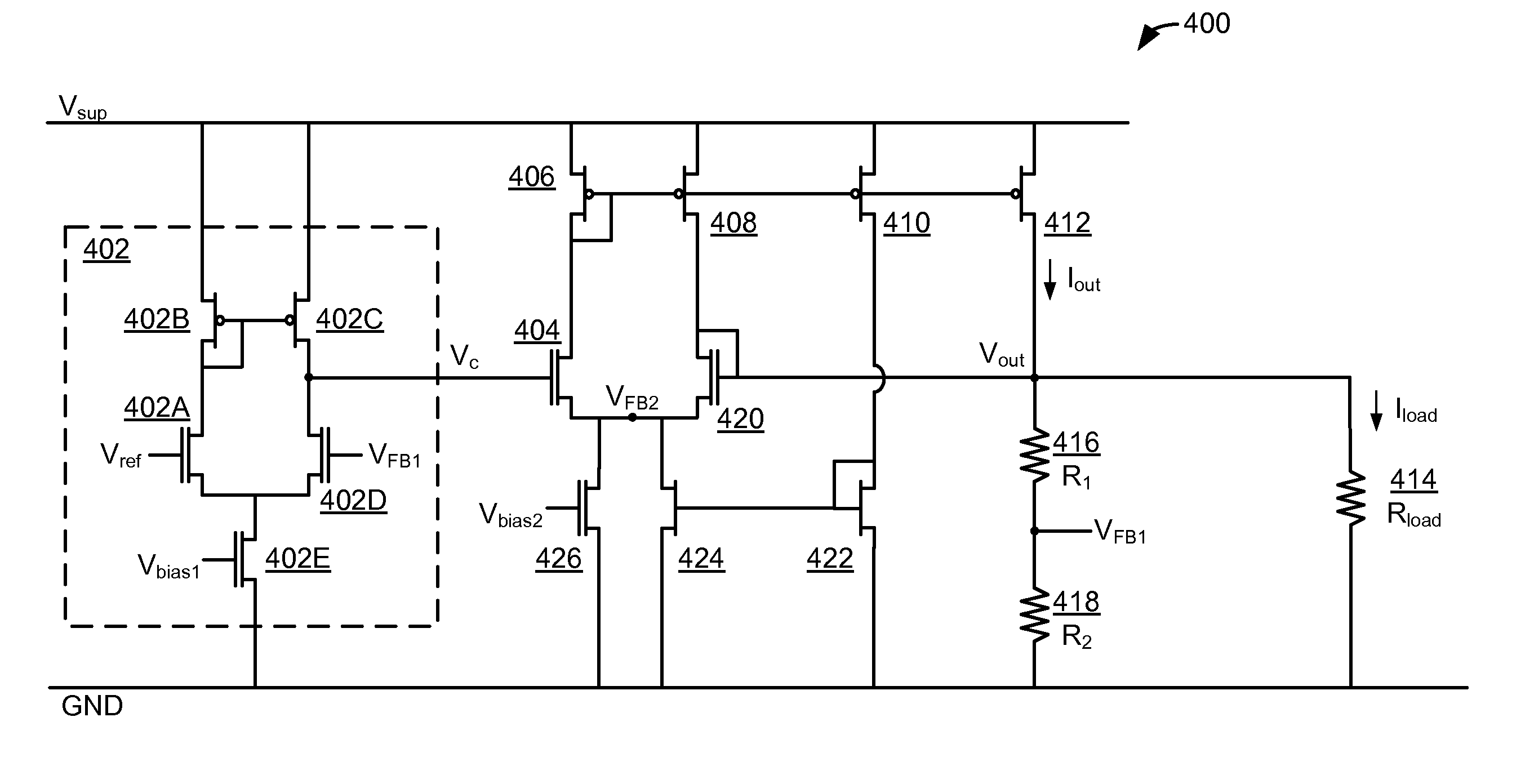
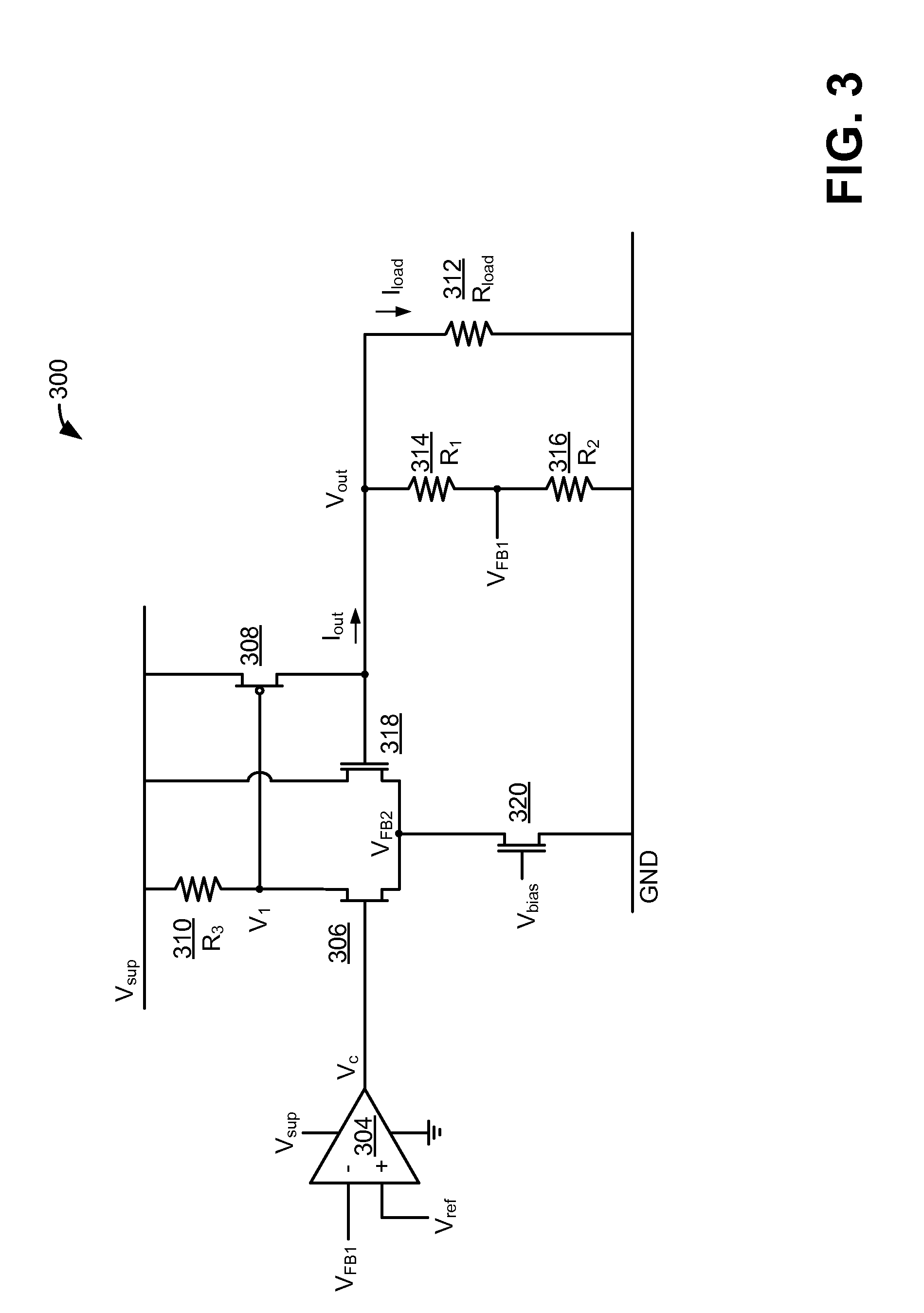
[0014]In one embodiment, there is provided a circuit arranged as a voltage regulator. The circuit comprises an output terminal to produce an output signal, a first feedback path to monitor the output signal to detect variations in the output signal and to adjust the output signal to compensate for the variations, and a second feedback path to monitor the output signal to detect the variations in the output signal and to adjust the output signal to compensate for the variations. The first feedback path is adapted to compare a level of the output signal to a reference signal identifying a desired level of the output signal. The second feedback path is adapted to respond to the variations in the output signal more quickly than the first feedback path.

Problems solved by technology

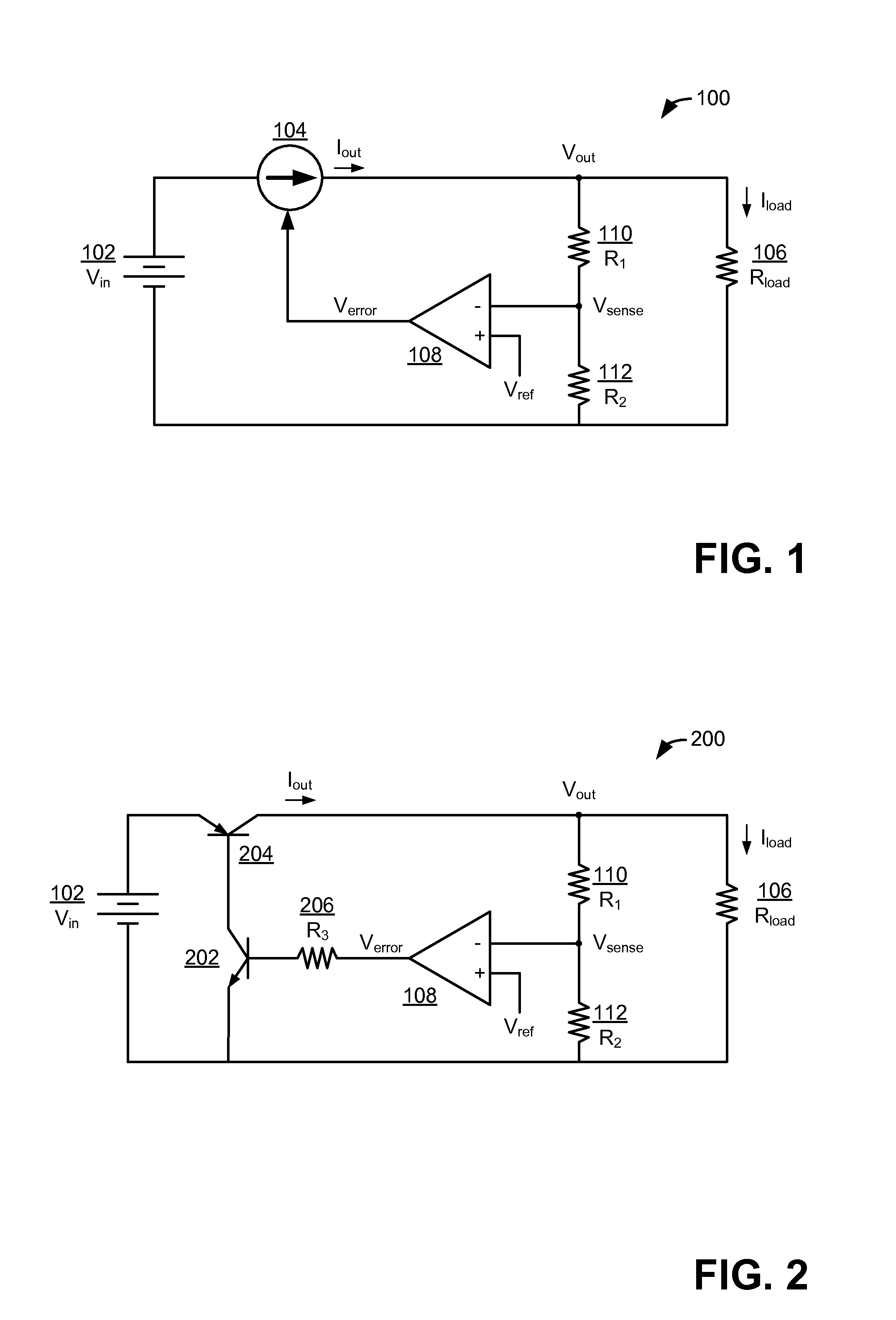
A circuit may function improperly when the supply voltage is not at the proper value.
Outside of those ranges, the feedback loop of the regulator that controls the current source will be unstable.
When unstable, the regulator cannot properly regulate the output voltage in responses to transients, and thus the voltage output Vout will continue to vary for a long time or indefinitely, causing a large or potentially infinite transient response time.
Linear voltage regulators that are used with circuits that change characteristics quickly or to a large degree are particularly susceptible to becoming unstable.
If characteristics of a load circuit change quickly as a result of a change in operations in a circuit, then the fast transient may cause the voltage regulator to become unstable and stop working properly.
Similarly, a large transient can cause instability in the regulator.

Method used


Image

  • Voltage regulator
  • Voltage regulator
  • Voltage regulator

Examples


Embodiment Construction

[0025]As discussed above, to enable conventional voltage regulators to operate stably and accurately for different loads, voltage regulators are typically implemented with one or more capacitors coupled to their output terminal. Applicants have recognized and appreciated, though, that such a modification may not stabilize a regulator or enable it to operate over a suitable load range. Further, Applicants have recognized and appreciated that as capacitors are added to the regulator circuit, the transient time of the regulator grows, which may reduce the regulators' ability to quickly control the output voltage. For regulators that include several capacitors and can operate over a very wide range of load circuits and characteristics, including regulators using Nested Miller Compensation (NMC) techniques, the transient response time can be very high. Regulators with high transient response times may not properly control the voltage output for fast transients, which can cause errors to ...


PUM


Abstract

Described herein are principles for designing and operating a voltage regulator that will function stably and accurately without an external capacitance for all or a wide range of load circuits and characteristics of load circuits. In accordance with some of these principles, a voltage regulator is disclosed having multiple feedback loops, each responding to transients with different speeds, that operate in parallel to adjust an output current of the regulator in response to variations in the output current / voltage due to, for example, variations in a supply voltage and / or variations in a load current. In this way, a voltage regulator can respond quickly to variations in the output current / voltage and can avoid entering an unstable state.

Description

RELATED APPLICATIONS[0001]This application claims the priority benefit of Indian provisional patent application number 1375 / Del / 2009, filed on Jul. 3, 2009, entitled “Capacitorless linear voltage regulator,” which is hereby incorporated by reference to the maximum extent allowable by law.BACKGROUND[0002]1. Field of Invention[0003]The techniques described herein relate generally to voltage regulators. Some embodiments relate to a voltage regulator having a fast transient response and operable over a range of load capacitances. The voltage regulator can operate over a range of load capacitances without an external capacitance to stabilize the regulator. Some embodiments relate to a low-dropout (LDO) voltage regulator operating without a stabilizing external capacitor.[0004]2. Discussion of Related Art[0005]Electronic circuits are often designed to operate using particular supply voltages. A circuit may function improperly when the supply voltage is not at the proper value.[0006]Voltag...

Claims


Application Information

Patent Timeline
IPC IPC(8): G05F1/10
CPCG05F1/575
Inventor BANSAL, NITINCHATTERJEE, KALLOL
Owner STMICROELECTRONICS INT NV
Learn More