
Efficient arrangement of membrane bioreactors

a bioreactor and efficient technology, applied in the direction of ultrafiltration, moving filter element filters, water/sludge/sewage treatment, etc., to achieve the effect of reducing costs, minimizing carbon footprint, and improving installation times

Active Publication Date: 2011-01-06
GLV FINANCE HUNGARY KFT A HUNGARIAN CO +1
View PDF8 Cites 6 Cited by
  • Summary
  • Abstract
  • Description
  • Claims
  • Application Information

AI Technical Summary

Benefits of technology

[0017]Allowing a multitude of entry (feed) and return (outlet) points has the significant benefit of forming well-defined continuous stirred tank reactors (CSTR) designed to prevent short-circuiting and the formation of MLSS / DO concentration gradients.
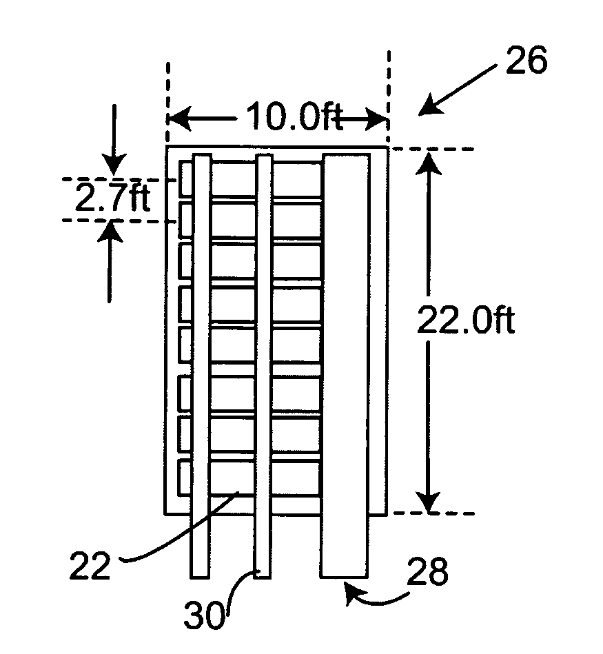
[0019]Instead of spacing membrane equipment to accommodate the needed conventional roll pattern, submerged membrane assemblies are pushed tightly together and a roll pattern is created through a common recycle wall using pipes, baffles or vanes. The recycle wall can be further compartmentalized to separate return flows from the IR needed for generating roll patters. By separating the two flows, tank levels can be adjusted without impacting roll patterns and draw off for return can be equalized along a reactor's full length despite numerous hydraulic jumps and vortexing that may occur with downward IR flow. This new arrangement can reduce volumetric space requirements by about 40% (compared to double-stacked prior arrangements).
[0022]Integrating the mixed liquor return and IR into one structure can eliminate the need for additional concrete walls. Less concrete can reduce costs, minimize carbon footprint and improve on installation times. The combined recycle wall structure can also be used to support tank covers. In package systems where submerged membrane assemblies are installed in tanks, the recycle wall can serve as structural support, improving the structural integrity of the tank and reducing seismic bracing requirements.

Problems solved by technology

However, such prior art generally refers to limited, discrete points usually identified as gates, wall cutouts, valves or other.

Method used


Image

  • Efficient arrangement of membrane bioreactors
  • Efficient arrangement of membrane bioreactors
  • Efficient arrangement of membrane bioreactors

Examples


Embodiment Construction

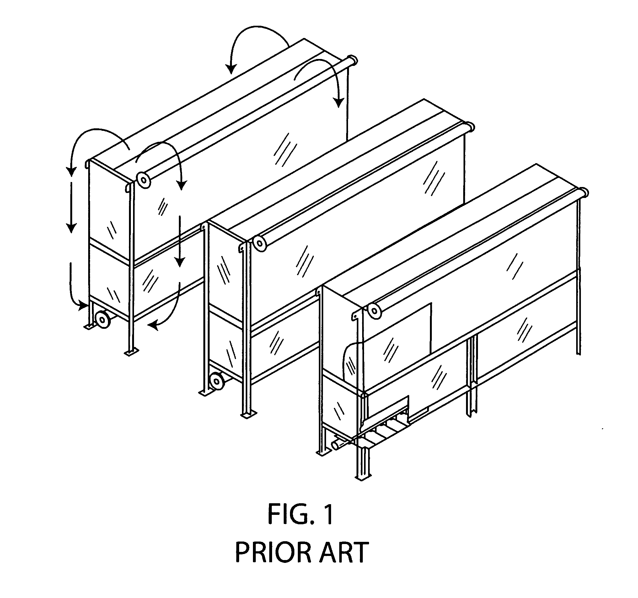
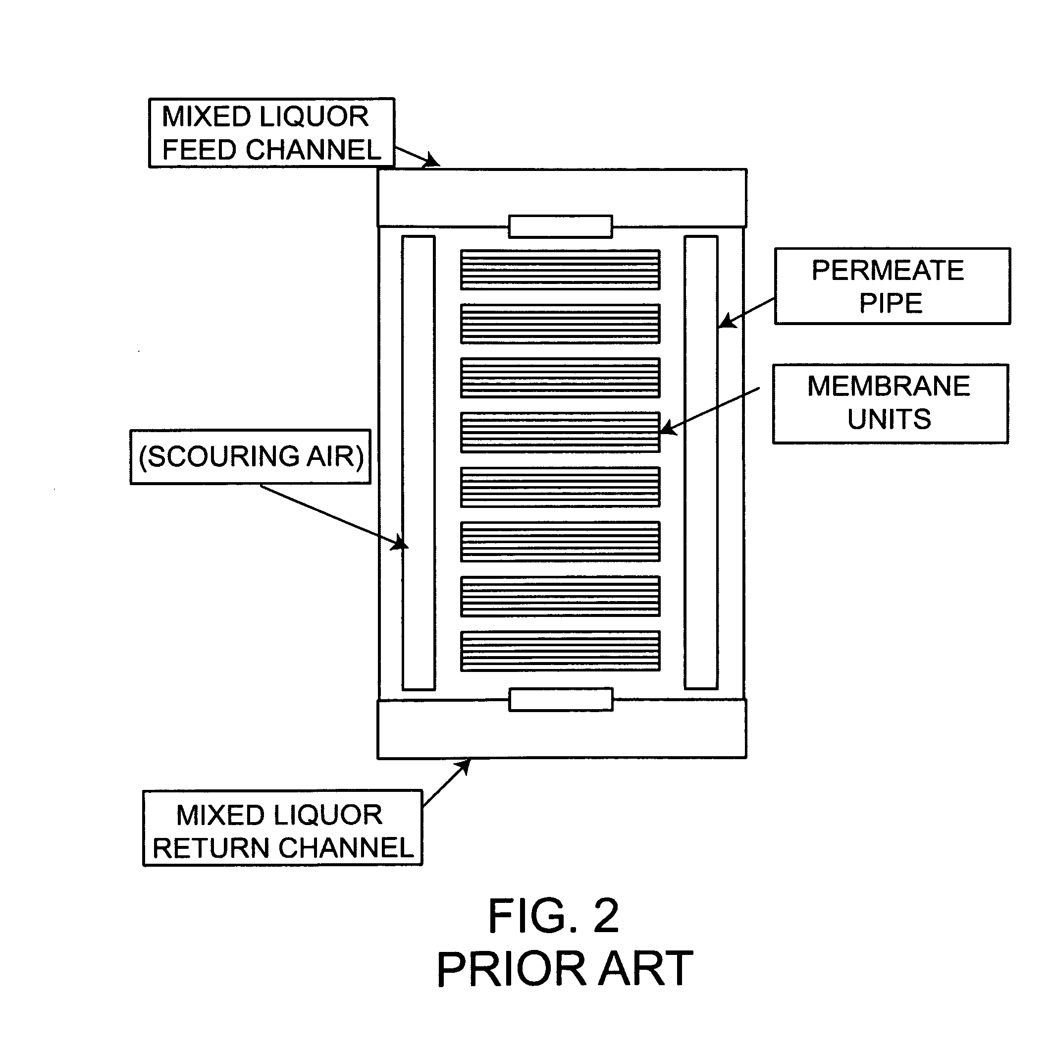
[0046]FIGS. 3A through 3F are further schematic diagrams for comparison of space requirements for membrane filtration units, here cassette type units, in accordance with prior art and in accordance with the invention. In FIGS. 3A and 3B eight cassettes are maintained in an MBR tank or zone 20, each cassette being shown at 22. These cassettes are stacked in a typical way, four lower cassettes, four upper cassettes. The cassettes are arranged with space between them, as at 23, to allow the typical roll pattern of internal recycle as discussed above. The double stacking of the cassettes requires a deep tank, shown here with a liquid level of about 16.5 feet. In this typical example scouring air is delivered to the zone through an air pipe 24 and a permeate pipe for permeate water is shown at 25, these two pipes being at opposite sides of the array or series of cassettes (positioned generally off the ends and above the individual cassettes 22). As is typical, the cassettes are spaced at...


PUM

PropertyMeasurementUnit
hydraulic residence timeaaaaaaaaaa
volumeaaaaaaaaaa
volumeaaaaaaaaaa

Abstract

Flat-sheet membrane filter assemblies require open space around equipment to form a viable path for an internal recycle or roll pattern. Creating a dedicated roll pattern for individual filter assemblies is space intensive and imposes process constraints on tank dimensions. A hollow wall or series of pipes forms a recycle wall designed to consolidate roll patterns and reduces space requirements. The recycle wall is designed such that the structural components also serve as a mixed liquor distribution system for the necessary roll pattern. Fixed vertically oriented conduit and sectional channel pieces allow for easy access and removal of membrane filter assemblies installed side by side. Feeding mixed liquor, air and or influent to the bottom of filter assemblies via submerged conduit improves process efficiency when coupled with return channels spaced not more than 10 feet away and above assemblies. The system is particularly advantageous for flat-sheet membrane filter units used in SMBR applications but is adaptable to other technologies including tubular and hollow-fiber membrane filter assemblies.

Description

BACKGROUND OF THE INVENTION[0001]The invention concerns flat-sheet membrane separators, especially as used in wastewater treatment or biosolids waste management systems. Specifically the invention encompasses an improved, more efficient arrangement of flat-sheet membrane assemblies as process cells in a tank, along with positioning of liquid piping and air conduits for space saving, energy saving and higher efficiency operation.[0002]Flat-sheet membrane technology has some inherent advantages over alternate technologies when used in submerged membrane bioreactor (SMBR) applications. In particular, flat-sheet technologies are generally considered easier to operate and more robust than hollow-fiber or tubular membrane systems. However, flat-sheet technology is generally less space and energy efficient than competing technologies due to low packing density and longer hydraulic residence times (HRT).[0003]Packing density is a measurement of space efficiency and is typically calculated b...

Claims


Application Information

Patent Timeline
Patent Type & Authority Applications(United States)
IPC IPC(8): B01D65/08B01D69/06
CPCB01D61/18B01D63/082C02F3/1273B01D2321/185B01D2315/06Y02W10/10B01D63/0821
Inventor LIVINGSTON, DENNIS
Owner GLV FINANCE HUNGARY KFT A HUNGARIAN CO
Learn More