Goniophotometer

a goniophotometer and goniophotometer technology, applied in the field of goniophotometers, can solve the problems of inability to easily influence the environmental temperature and air motion, large error, and constant change of detected beams, and achieve the effect of less occupied area and higher measuring accuracy

Active Publication Date: 2010-12-30
HANGZHOU ZHEJIANG UNIV SENSING INSTR
View PDF1 Cites 15 Cited by
  • Summary
  • Abstract
  • Description
  • Claims
  • Application Information

AI Technical Summary

Benefits of technology

[0009]1. The sync-mirror synchronously rotating with the main mirror is adopted, which can eliminate the influence for the measuring results from the directivity of the mirror;
[0010]2. it is easy to position the diaphragm in the light channel to eliminate the stray light;
[0012]4. the goniophotometer of the invention has the advantages of less occupied area and higher measuring accuracy.

Problems solved by technology

Therefore, it cannot be easily influenced by the environmental temperature and the air motion; the disadvantages are that: the detected beam is changed with the cone and the detected distance is fixed.
In addition, since the detector is fixed and cannot follow the rotation, the sensitivity difference of the detector in different directions of the space can lead to a relatively big error.
The advantage is that: the luminaire under test has a fixed space position, which is not easily to be influenced by the environmental temperature and the air motion; the disadvantage is that: the detected beam is always changing while rotating around the cone.
Since the detector and the moving mirror are moving synchronously, it is difficult to arrange a series of diaphragms for eliminating the stray light between the detector and the light source.
Since the reflectance of the mirror in each direction of the space are discord, the obvious luminous intensity error will be introduced; besides, the surface shape error of the fixed mirror will cause that the detecting accuracy of the luminous intensity is sensitively influenced by the surrounding reflected stray light.

Method used


Image

  • Goniophotometer
  • Goniophotometer
  • Goniophotometer

Examples


Embodiment Construction

[0023]In order to clarify the substantial characteristics of the invention, more detailed description is given below with a combination of the attached figures of the specification and the specific implementation methods.

[0024]A detailed description is given below with a combination of the attached figures.

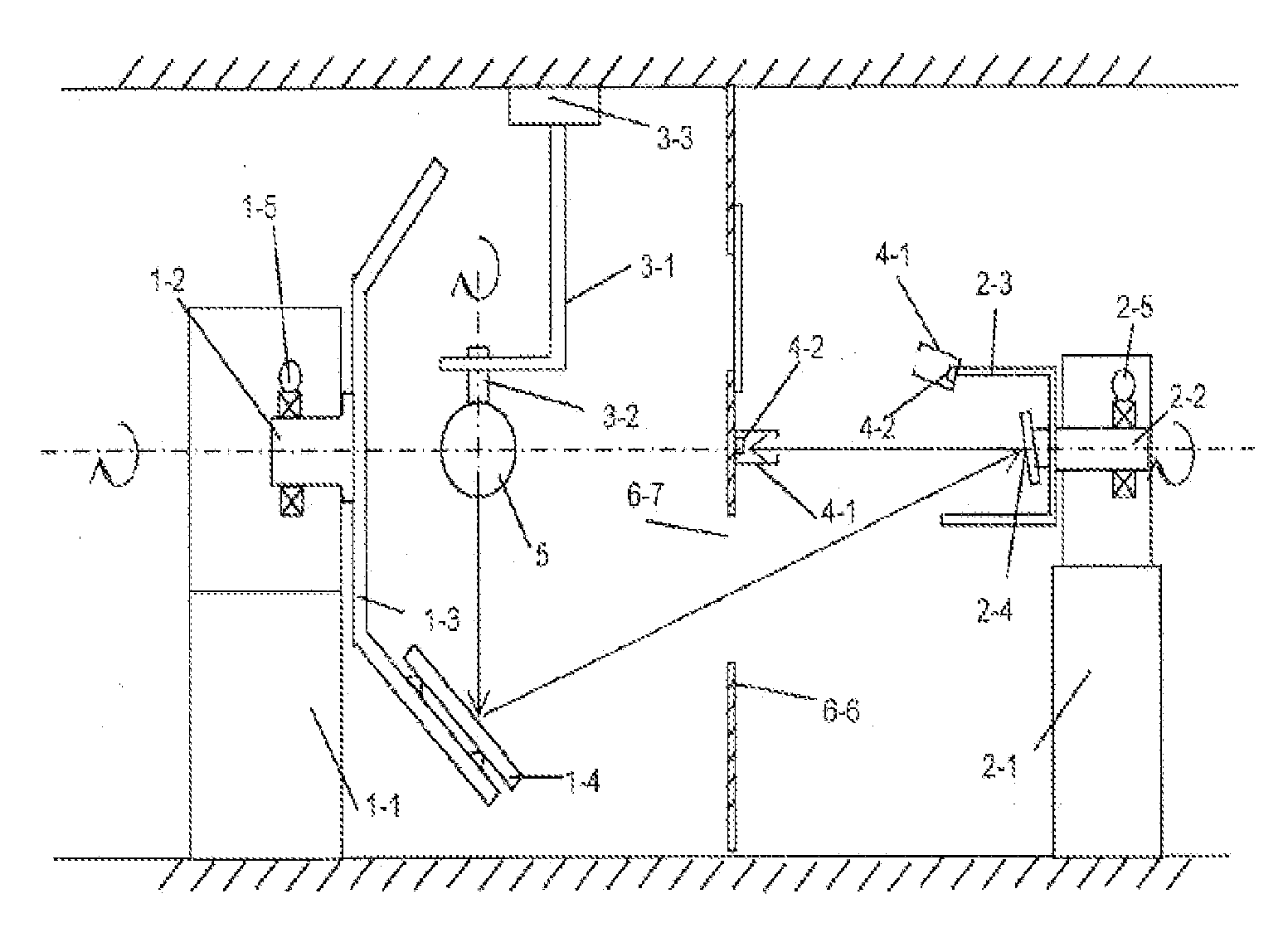
[0025]As shown in FIG. 1, the goniophotometer comprises the main rotating table, the sync-rotating table, the luminaire rotating table and the light detecting tubes; the main rotating table comprises: the main base 1-1 and the main rotating axis 1-2 installed on the main base 1-1. The main rotating axis 1-2 and the main mirror arm 1-3 are tightly fixed. The main mirror 1-4 is installed on the main mirror arm 1-3; the sync-rotating table comprises: the sync-base 2-1 and the sync-rotating axis 2-2 installed on the sync-base 2-1. The sync-rotating axis 2-2 and the main rotating axis 1-2 are coincident. The sync-mirror arm 2-3 is installed on the sync-rotating axis 2-2. The sync-mirro...


PUM


Abstract

A goniophotometer has a main rotating table, a sync-rotating table, a luminaire rotating table and light detecting tubes (4-1, 4-2). The main rotating table has a main rotating axis (1-2) and a main mirror (1-4) reflecting the light from a luminaire under test (5). The sync-rotating table has a sync-rotating axis (2-2) and a sync-mirror (2-4) located in the reflection path of the main mirror (1-4). The sync-rotating axis (2-2) is coincident with the main rotating axis (1-2). The luminaire rotating table has a luminaire rotating axis (3-2) which can drive the rotation of the luminaire under test (5). The luminaire rotating axis (3-2) is perpendicular to the main rotating axis (1-2). The light detecting tubes (4-1, 4-2) are arranged in the emergent light path to detect the luminous intensity of the luminaire under test (5) in different direction.

Description

FIELD OF THE INVENTION[0001]The invention relates to a goniophotometer, in particular to a goniophotometer with a main mirror and a synchronization mirror.BACKGROUND OF THE INVENTION[0002]The common goniophotometers with the mirrors can be classified into the following three types: The first one is the goniophotometer with rotating-mirror. A photo-detector is fixed in this goniophotometer. The luminous intensity of the luminaire under test in different directions can be detected through the autorotation of the mirror and the circumferential moving and autorotation in the space of the luminaire under test. As the luminaire under test is moving during the detecting process and the luminaire under test is in different environments with different positions, it is easily to be influenced by the environmental temperature and the air motion.[0003]The second one is the goniophotometer with moving-mirror. The photo-detector is fixed or rotated with the moving mirror. With the mirror rotating...

Claims


Application Information

Patent Timeline
IPC IPC(8): G01N21/47
CPCG01J1/02G01J1/0214G01J1/0271G01J2001/4247G01J1/0403G01J1/0414G01J1/06G01J1/04
Inventor MOU, TONGSHENG
Owner HANGZHOU ZHEJIANG UNIV SENSING INSTR
Why Eureka
Try Eureka