Safety system for safeguarding a moving, guided motion element against unwanted collisions

a safety system and moving technology, applied in the direction of door/window protective devices, instruments, wing accessories, etc., can solve the problems of undesired blocking of monitoring beams, successive no longer available object detection monitoring beams of light curtains, etc., and achieve the effect of reducing the risk of injury

Inactive Publication Date: 2010-12-30
CEDES AG
View PDF3 Cites 11 Cited by
  • Summary
  • Abstract
  • Description
  • Claims
  • Application Information

AI Technical Summary

Benefits of technology

[0006]The invention is based on a safety system for safeguarding a moving, guided motion element, for example, a door or a door element, against unwanted collisions with an object located on a motion path in the direction of motion of the motion element. The safety system comprises an object-detection device for detecting an object in an area of the motion element, which object-detection device can be blocked with respect to object detection by a motion of the motion element, and has an electronic unit with which the motion of the motion element can be controlled and which is configured to assign a blocked state to the object-detection device when the motion element approaches, in which blocked state an object or motion element does not trigger a safety mode. For this purpose, a shut-off mechanism is provided which, when a shut-off signal coming from the motion element is detected, transfers at least part of the object-detection device into the blocked state. The core of the invention is then the fact that the shut-off mechanism comprises a transmitting element for a shut-off signal which is either seated directly on the motion element or is tuned to a separate reflector for electromagnetic radiation, in particular an optical reflector on the motion element, in such a way that a signal of the transmitting element can be received by a receiver of the shut-off mechanism only in a predefined motion area of the reflector on the motion element. This procedure makes it possible to avoid a reflection of an object being interpreted as a shut-off signal and the object-detection device or at least part thereof therefore being incorrectly shut off.
[0032]The individual components of the safety system on one side of the motion element do not necessarily have to be accommodated in one structural unit. It is conceivable that, for example, individual sensor pairs or groups of sensors which communicate via a bus are mounted. This permits a greater degree of flexibility to be achieved if the object-detection device and / or shut-off mechanism of the safety system are to be adapted to different structural conditions, in particular relatively small or relatively large monitoring areas.

Problems solved by technology

In this way, the monitoring beams of the light curtain are successively no longer available for object detection during a closing motion of the door.
However, in such a configuration it is conceivable that an object which is to be detected is incorrectly interpreted as an approaching door and could therefore bring about undesired blocking of monitoring beams.

Method used


Image

  • Safety system for safeguarding a moving, guided motion element against unwanted collisions
  • Safety system for safeguarding a moving, guided motion element against unwanted collisions
  • Safety system for safeguarding a moving, guided motion element against unwanted collisions

Examples


Embodiment Construction

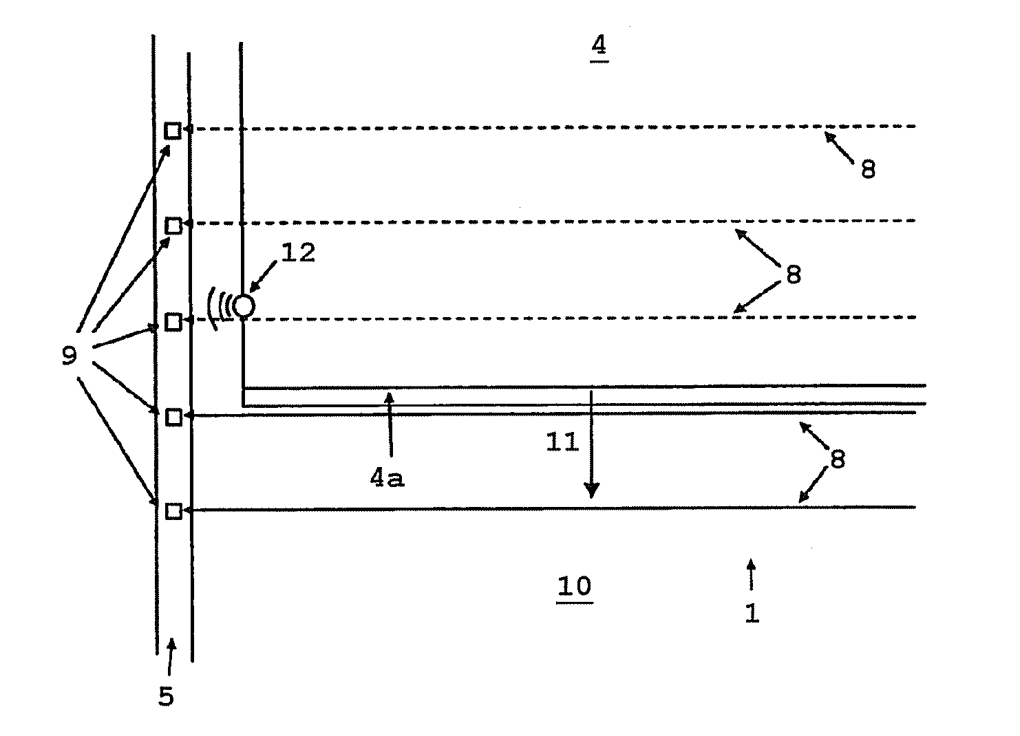
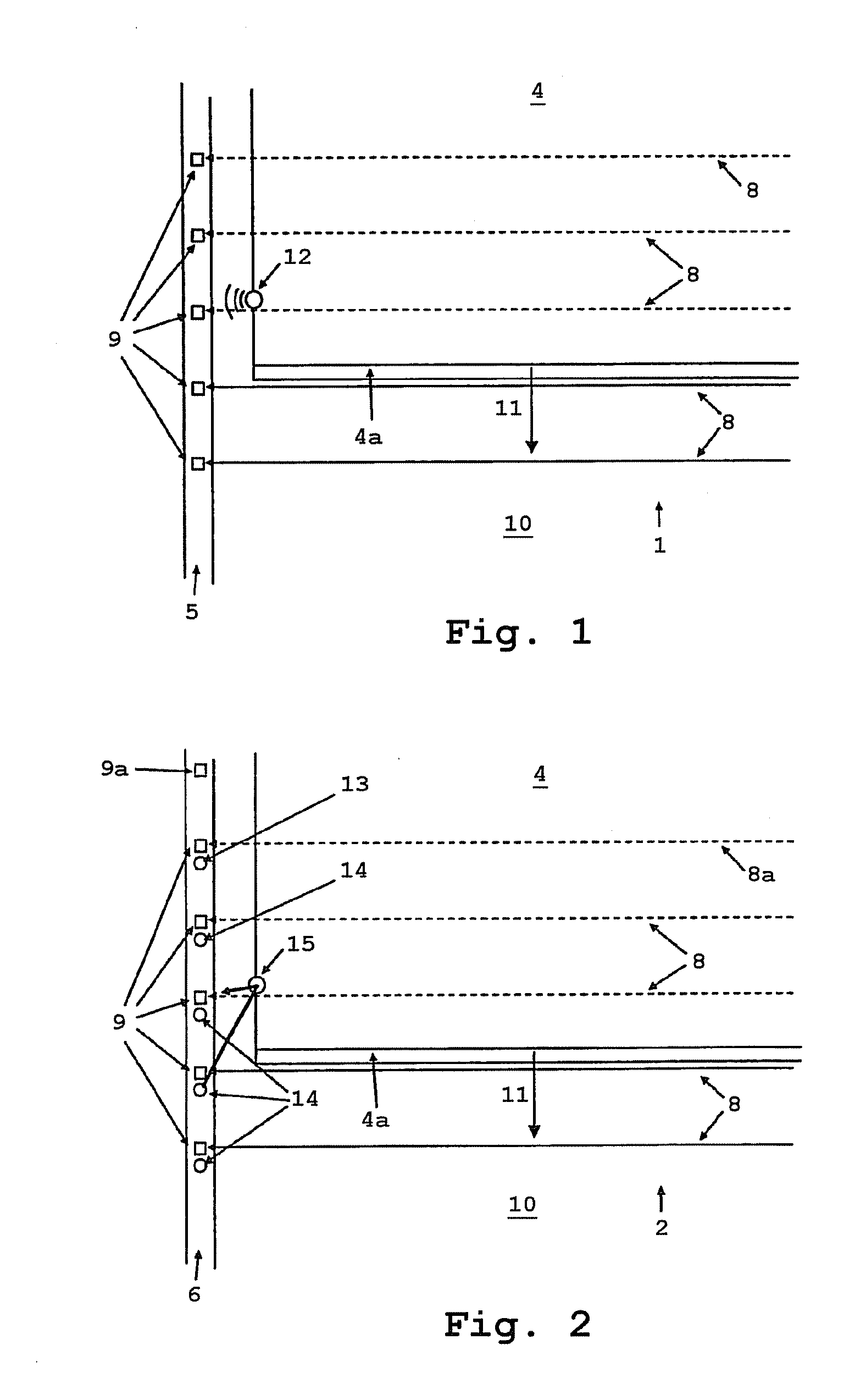
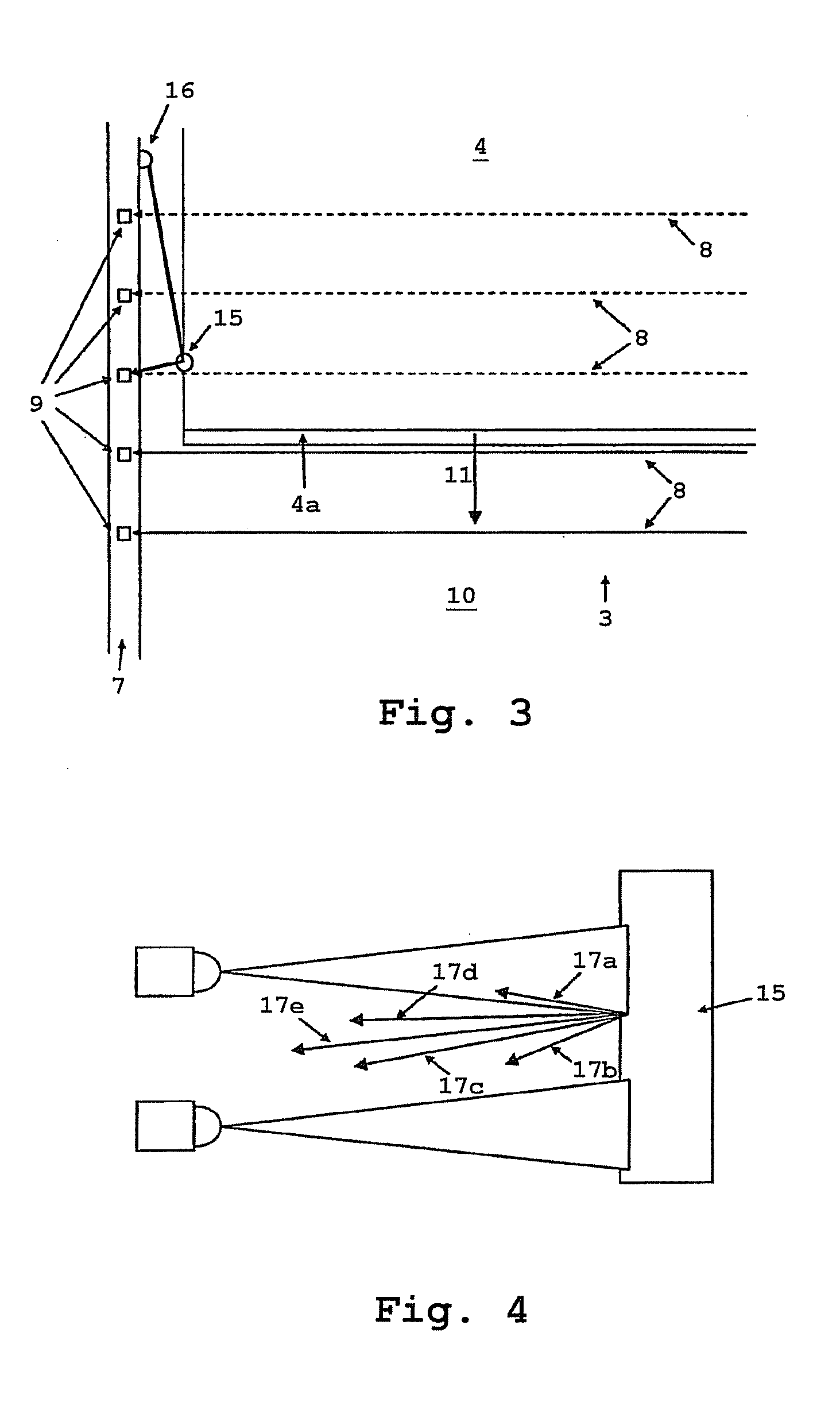
[0039]FIGS. 1-3 each show the left-hand side of different door safety systems 1, 2, 3. In each case the left-hand, lower corner of a door element 4 is represented in a schematic form. The door safety systems 1, 2, 3 each comprise, on the left-hand side, a receiver strip 5, 6, 7. The associated transmitters, which emit monitoring light beams 8 to, in each case, one receiver 9, are not illustrated in FIGS. 1-3. The monitoring light beams 8 ensure that when an object enters an area 10 underneath a front edge 4a of the door element 4, an interruption in the monitoring light beams 8 causes the door element 4 to stop and, if appropriate, reverse in order to prevent collisions with the object.

[0040]However, when the door element 4 moves down it is to be ensured that the door element 4 does not itself trigger a safety mode because the door has interrupted a monitoring light beam 8. This can be achieved in that, before the respective monitoring light beam 8 is reached by the front edge 4a of...


PUM


Abstract

A safety system for safeguarding a moving, guided motion element against unwanted collisions with an object located on a motion path in the direction of motion of the motion element is proposed, which safety system comprises an object-detection device for detecting an object in an area of the motion element. The object-detection device can be blocked with respect to object detection by a motion of the motion element, and has an electronic unit with which the motion of the motion element can be controlled and which is configured to assign a blocked state to the object-detection device when the motion element approaches, in which blocked state an object or motion element does not trigger a safety mode, wherein shut-off mechanism are provided which, when a shut-off signal coming from the motion element is detected, transfer at least part of the object-detection device into the blocked state.

Description

CROSS REFERENCE TO RELATED APPLICATIONS[0001]This application is a continuation of International Application No. PCT / EP2009 / 000276 filed Jan. 16, 2009, which designated the United States, and claims the benefit under 35 USC §119(a)-(d) of German Application Nos. 10 2008 004 760.0 filed Jan. 16, 2008, 10 2008 013 844.4 filed Mar. 12, 2008 and 10 2008 023 294.7 filed May 13, 2008, the entireties of which are incorporated herein by reference.FIELD OF THE INVENTION[0002]The invention relates to safety system for safeguarding a moving, in particular vertically moving, guided motion element against unwanted collisions.BACKGROUND OF THE INVENTION[0003]European Patent No. 0 902 157 B1 discloses safeguarding doors with a light curtain which is mounted in the plane of motion of a door. So that the door is not detected as an object, monitoring beams of the light curtain are blocked with respect to object detection by, in each case, a monitoring beam lying behind in the direction of motion of t...

Claims


Application Information

Patent Timeline
IPC IPC(8): E05F15/20
CPCE06B9/88E05Y2800/21E05F2015/436E05F15/43E05F15/74E05Y2800/242E05Y2900/106E05Y2900/00E06B2009/6836
Inventor DE COI, BEATSIGNER, CHRISTIANMENZI, MARKUSHUG, RENE
Owner CEDES AG
Why Eureka
Try Eureka