
Method for determining a time course of an accident occurring in a risk-prone installation

Inactive Publication Date: 2010-12-23
COMMISSARIAT A LENERGIE ATOMIQUE ET AUX ENERGIES ALTERNATIVES
View PDF4 Cites 4 Cited by
  • Summary
  • Abstract
  • Description
  • Claims
  • Application Information

AI Technical Summary

Benefits of technology

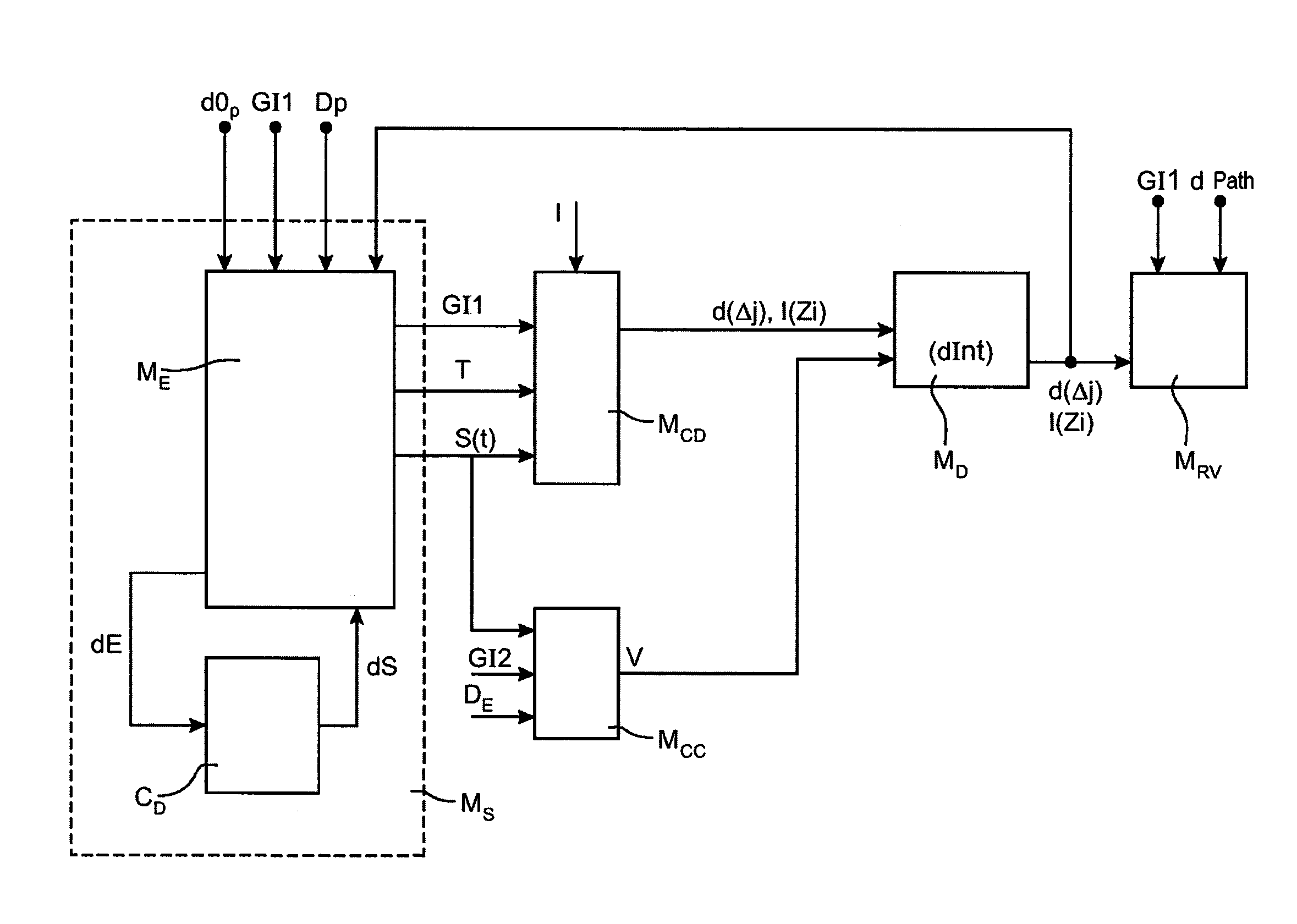
[0018]The very short aforementioned calculation time is obtained by using a method different from that of the prior art. The calculations performed within the scope of the invention, use interpolation of results tabulated beforehand. In the case, for example, of a nuclear installation, the thereby formed tables correlate characteristics of the radioactive radiation source, geometrical data (such as wall thicknesses) or physical characteristics of materials with the resulting effect on the path of radioactive radiations. In this way, the calculation time is considerably reduced. Typically, the calculation of the path of a radioactive particle over a distance of a few tens of meters is thereby performed within a few seconds, a duration which should be compared with the few hours required with Monte-Carlo type software packages used according to the prior art.
[0024]By making available representative parameterizable models of the installation and of the processes in progress in this installation, the method of the invention allows optimum management of the intervention with view to stopping the accident in order to limit the impact on personnels and / or the environment.

Problems solved by technology

The consequences of an accident with a time course generally tend to worsen with the elapsed time.
When an accident occurs at one or several processes in progress in the installation, one or more sources emitting harmful substances appear in this installation.
Such durations are detrimental to proper management of the accident.
In the short term, decisions from the team managing the accident may lead to engaging actions which may endanger the persons designated for intervening and / or to degradation of the relevant installation.

Method used


Image

  • Method for determining a time course of an accident occurring in a risk-prone installation
  • Method for determining a time course of an accident occurring in a risk-prone installation
  • Method for determining a time course of an accident occurring in a risk-prone installation

Examples


Embodiment Construction

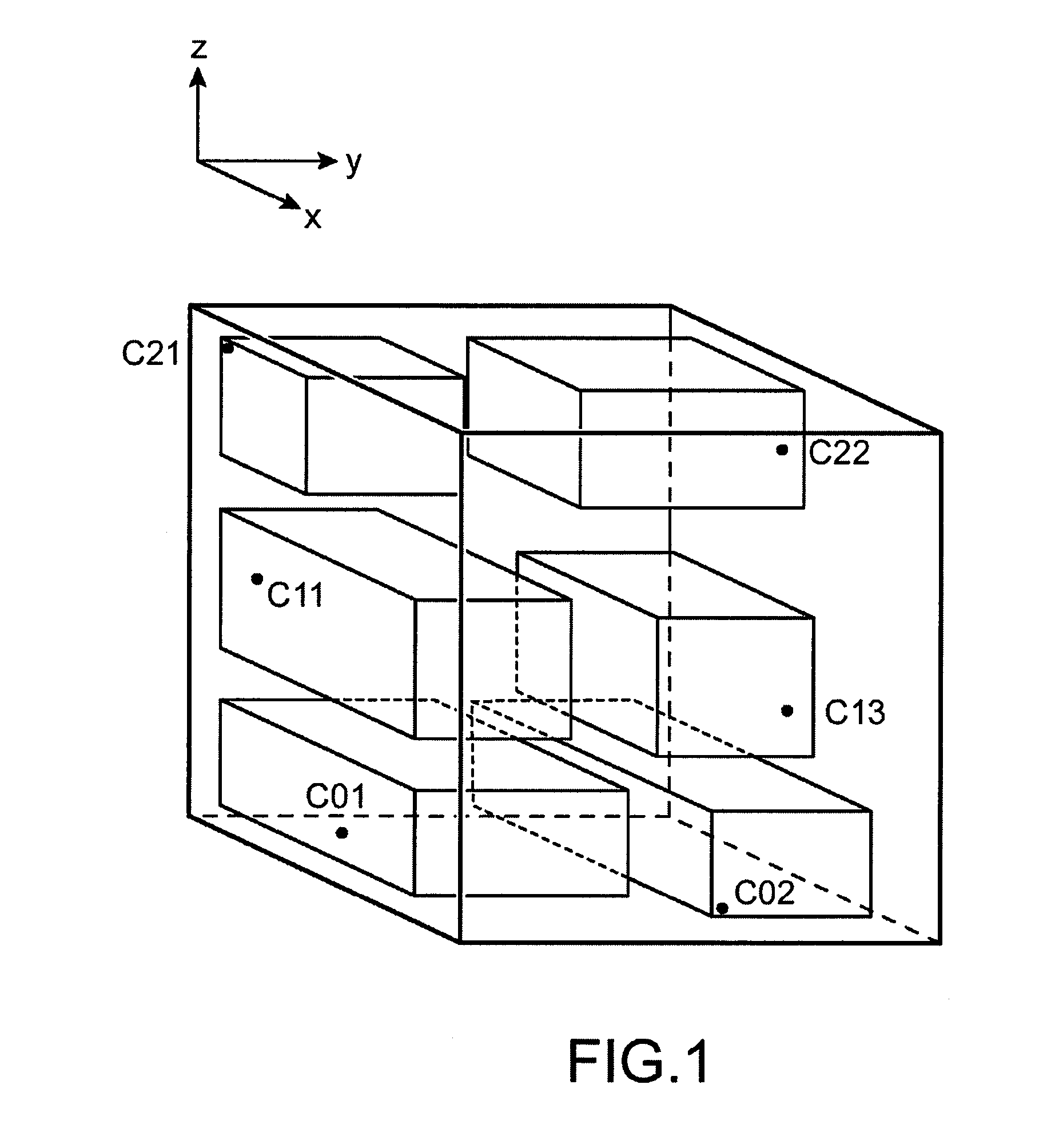
[0039]FIG. 1 symbolically illustrates an exemplary risk-prone installation in which an accident with a time course may occur.

[0040]The installation for example, consists of a multi-story building, each story comprising several rooms. Different measurement sensors Cnm are distributed in the different rooms of the installation. The sensors Cnm are intended to conduct radiation measurements with which the position of the source(s) which emit(s) a harmful substance and the nature of this harmful substance may be identified. In the case of a nuclear installation, the sensors Cnm for example are gamma sensors or neutron counters. The installation is located in a direct reference system (x, y, z) such that the z axis is the vertical axis along which is defined the height of the installation and the plane (x, y) is a horizontal plane for the installation.

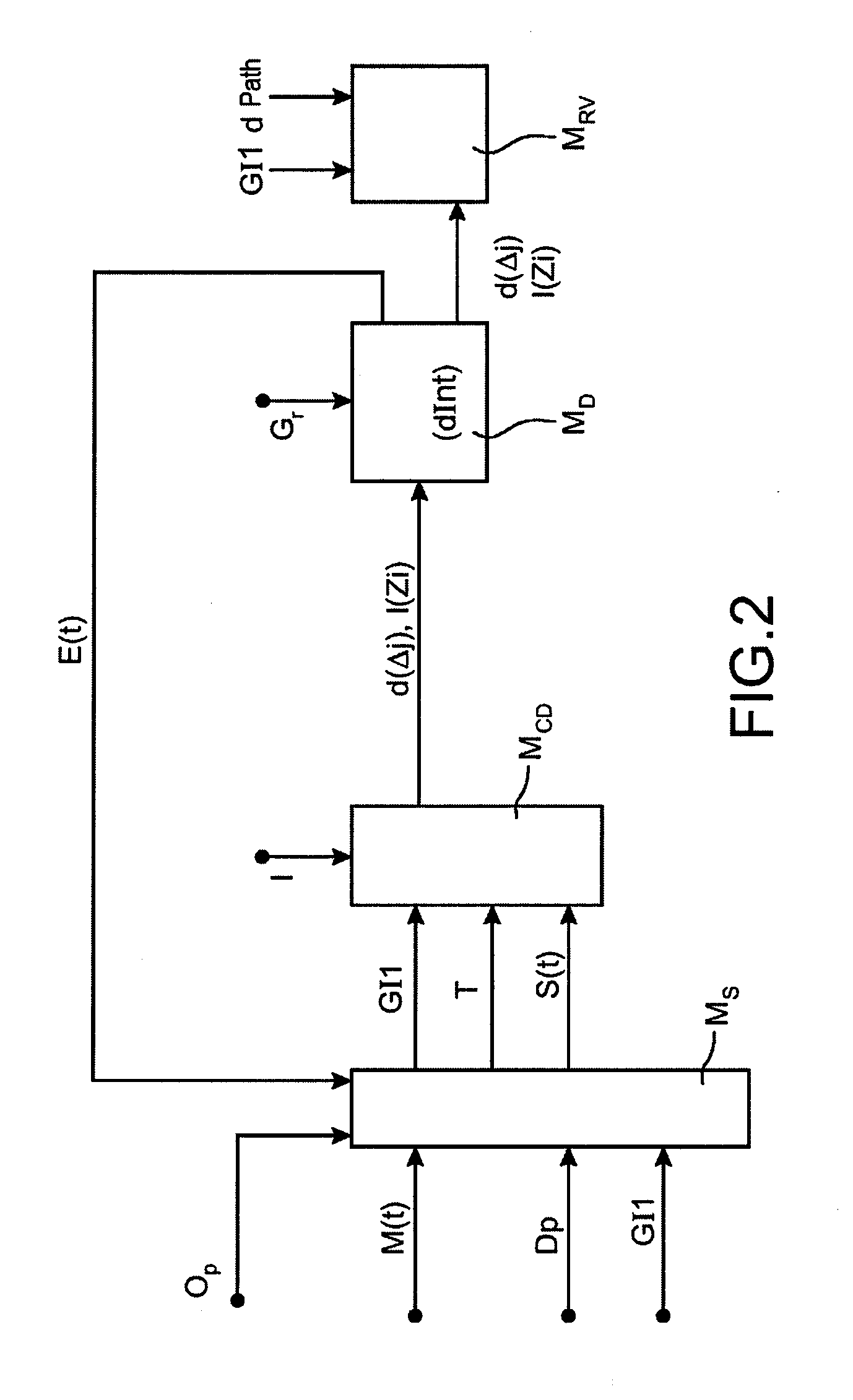
[0041]FIG. 2 illustrates the general block diagram of a device which applies the method of the invention in the case when a criticality ac...


PUM


Abstract

A method for determining a time course of an accident which occurs inside an installation in which takes place at least one risk-prone process, characterized in that it comprises: (a) a step (MS) for determining a source term (S(t)) which identifies a source at the origin of the accident and which comprises rate data of a harmful substance emitted by the identified source, (b) a step (Mcd) for calculating in real time, amounts of the harmful substance present in different points of the installation, from said rate and from geometrical data (GI1) of the installation, and (c) a diagnostic step (MD) at the end of which a datum (dInt) of feasibility or non-feasibility of intervention in the installation is delivered, after analysis of the time-dependent variations of the amounts calculated in the calculation step.

Description

TECHNICAL FIELD AND PRIOR ART[0001]The invention relates to a method for determining a time course of an accident which occurs in a risk-prone installation.[0002]By risk-prone installation, should be meant a building or set of buildings in which processes are in progress and which have risks for humans and / or the environment. For example, this may be a nuclear plant or a chemical plant. By accident with a time course, is meant any accident, the source term of which changes over time. As this will be specified subsequently, the source term is a set of data which describe a source or sources which are identified as emitting one or more harmful substances in the installation, following the accident.[0003]The consequences of an accident with a time course generally tend to worsen with the elapsed time. For example, this is the case of a fire which propagates in a building. When an accident occurs at one or several processes in progress in the installation, one or more sources emitting h...

Claims


Application Information

Patent Timeline
IPC IPC(8): G06F17/10G06F7/60
CPCG08B31/00G08B21/12
Inventor MASSE, VERONIQUECHIRON, MAURICE
Owner COMMISSARIAT A LENERGIE ATOMIQUE ET AUX ENERGIES ALTERNATIVES
Learn More