
Methods of recycling carbon dioxide to the gasification system

Active Publication Date: 2010-12-23
AIR PROD & CHEM INC
View PDF28 Cites 32 Cited by
  • Summary
  • Abstract
  • Description
  • Claims
  • Application Information

AI Technical Summary

Benefits of technology

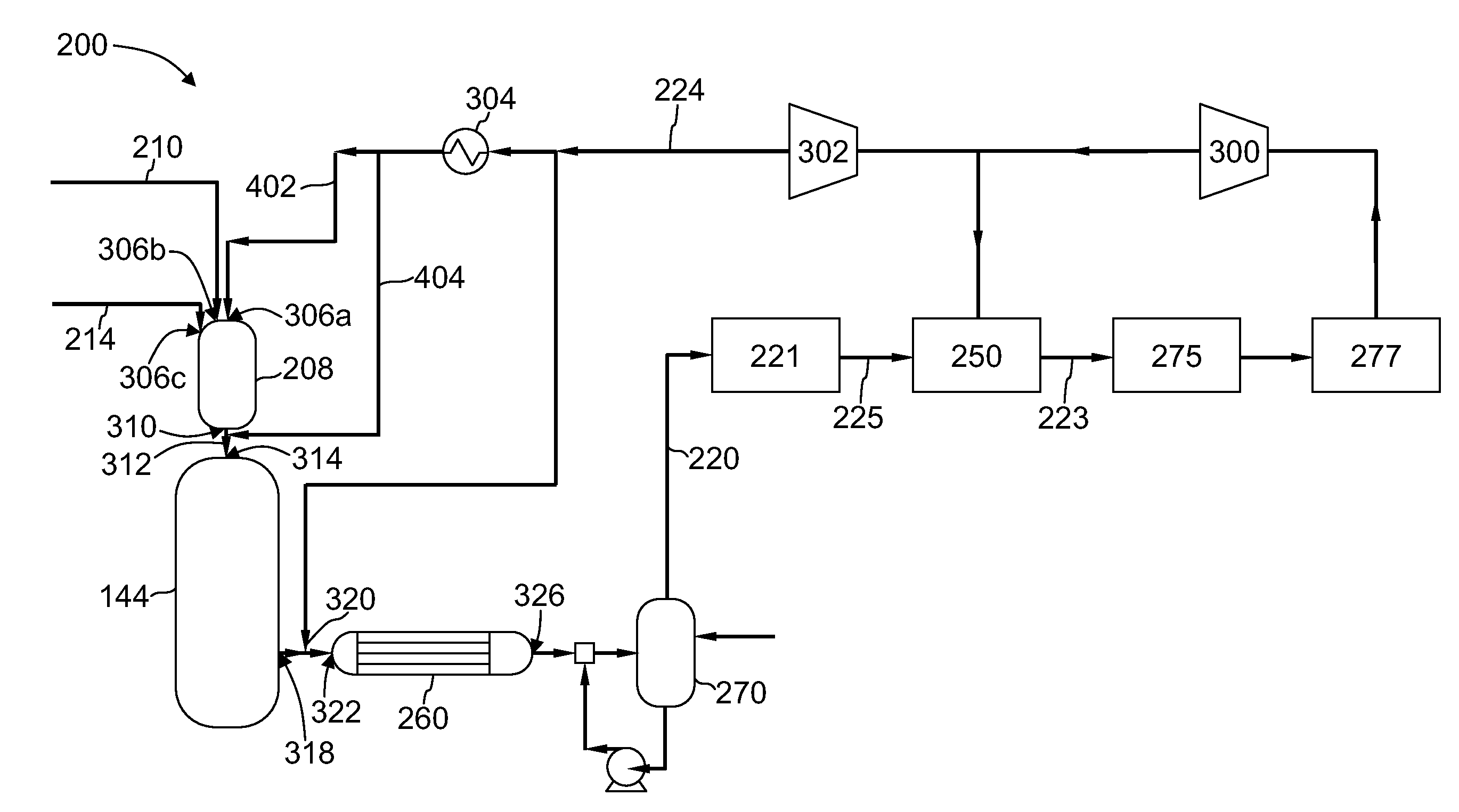
[0004]It has now been discovered, surprisingly, that by recycling carbon dioxide-rich gas to a gasifier in gasifying systems such as used in an IGCC plant, the oxygen from the carbon dioxide-rich gas participates in the gasification reactions, and facilitates reducing oxygen consumption and increasing carbon conversion. Both reduced oxygen consumption and higher carbon conversion facilitate increased IGCC plant efficiency. Mixing carbon dioxide-rich gas with hot syngas at the inlet of a radiant syngas cooler as described herein, favorably alters the reverse water gas shift reaction, such that the carbon dioxide reacts endothermically with hydrogen in the syngas to facilitate producing more carbon monoxide. Increased carbon monoxide facilitates reduced hydrogen consumption, and increased IGCC efficiency.
[0006]In another aspect, a method of recycling carbon dioxide from a first syngas mixture of a gasification system is provided. The method includes removing carbon dioxide-rich gas from the first syngas mixture in a separation device; compressing the carbon dioxide-rich gas; producing a second syngas mixture in a gasifier; mixing the second syngas mixture and at least a first portion of the compressed carbon dioxide-rich gas to form a combined syngas mixture; and introducing the combined syngas mixture into a radiant syngas cooler to facilitate cooling the second syngas mixture.
[0007]In a further aspect, a method of recycling carbon dioxide from a first syngas mixture of a gasification system is provided. The method includes removing carbon dioxide-rich gas from the first syngas mixture in a separation device; compressing the carbon dioxide-rich gas; producing a second syngas mixture in a gasifier; mixing the second syngas mixture and at least a first portion of the compressed carbon dioxide-rich gas to form a combined syngas mixture and introducing the combined syngas mixture into a convective syngas cooler to facilitate cooling the second syngas mixture.

Problems solved by technology

However, in such processes, no benefits have been achieved with regard to reduced oxygen consumption or improved carbon conversion with a gaseous feedstock.

Method used


Image

  • Methods of recycling carbon dioxide to the gasification system
  • Methods of recycling carbon dioxide to the gasification system
  • Methods of recycling carbon dioxide to the gasification system

Examples


Embodiment Construction

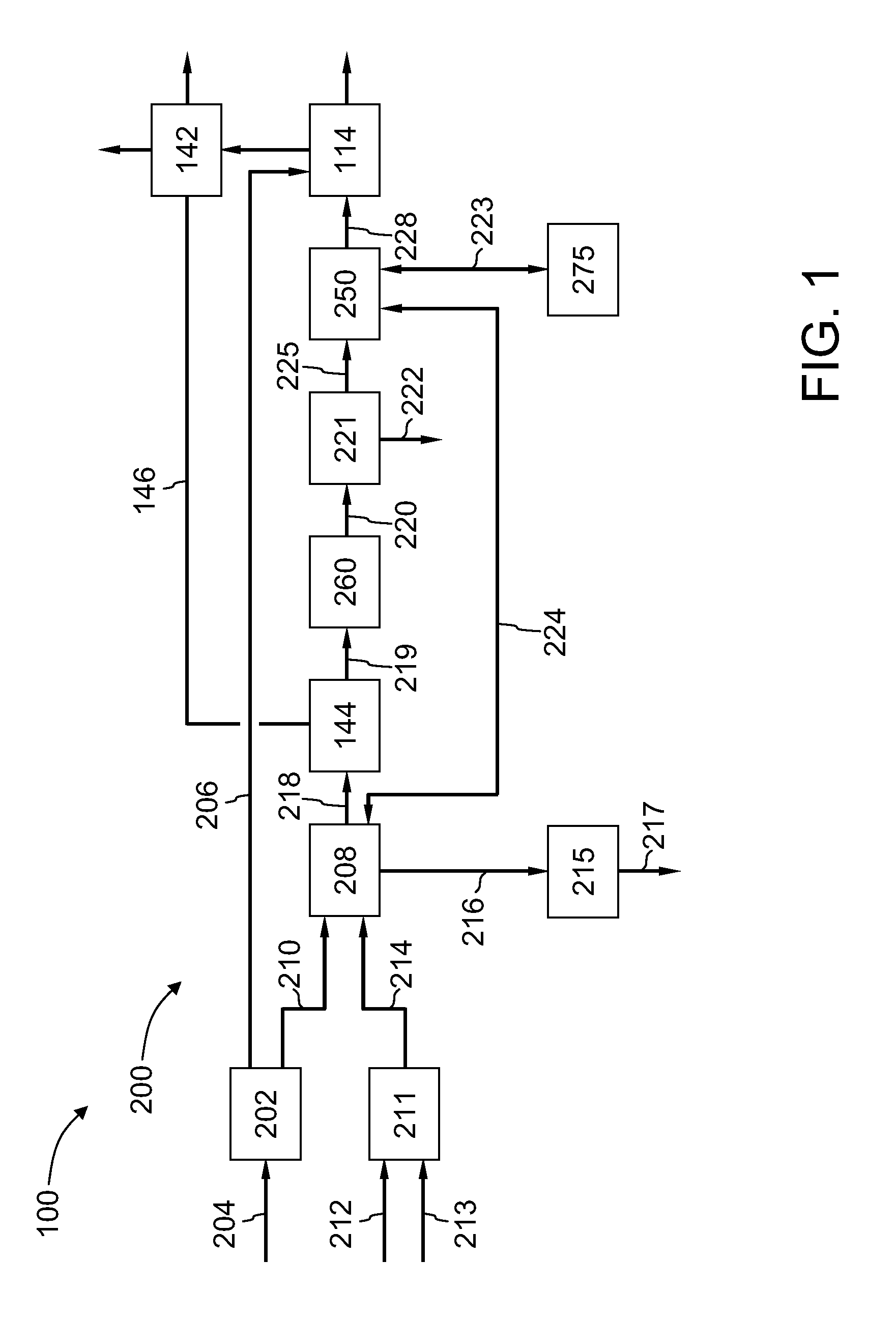
[0010]FIG. 1 is a schematic diagram of an exemplary integrated gasification combined-cycle (IGCC) power generation plant 100. FIG. 2 is a schematic diagram illustrating exemplary processes of the invention. While FIG. 1 depicts only a portion of IGCC plant 100, it should be understood by one skilled in the art that the methods as described herein can be used in a complete IGCC plant (including at least one steam turbine engine and an electrical generator) and / or in structurally similar IGCC plants as known in the art.

[0011]Furthermore, it should be understood by one skilled in the art that while described herein with an IGCC power generation plant, the present invention can be used with any known separation and / or gasification system without departing from the scope of the present invention. More particularly, systems including separation devices for providing physical and / or chemical separation, pressure-swing adsorption, temperature-swing adsorption, membrane separation, and the l...


PUM

PropertyMeasurementUnit
Fractionaaaaaaaaaa
Fractionaaaaaaaaaa
Fractionaaaaaaaaaa

Abstract

Method of producing syngas in an IGCC system, comprising compressing and heating carbon dioxide-rich gas to produce heated compressed carbon dioxide-rich gas, mixing the heated compressed carbon dioxide-rich gas with oxygen and feedstock to form a feedstock mixture, subjecting the feedstock mixture to gasification to produce syngas, cooling the syngas in a radiant syngas cooler, contacting syngas cooled in the radiant syngas cooler with compressed carbon dioxide-rich gas to further cool the syngas, and removing an amount of carbon dioxide-rich gas from the product mixture and compressing the removed carbon dioxide-rich gas prior to mixing with oxygen and feedstock.

Description

[0001]The present invention relates generally to improvements in operations of an integrated gasification combined cycle plant, and more specifically to methods of recycling supplied carbon dioxide-rich gas from syngas to a gasifier and / or a radiant syngas cooler inlet after heating.BACKGROUND OF THE INVENTION[0002]In at least some known integrated gasification combined cycle systems (IGCC), carbon dioxide (and, more generally, carbon dioxide-rich gas) removed from syngas is vented or is used for the production of chemicals, and is typically not recycled to the gasifier (also referred to herein as gasification reactor). In those systems wherein carbon dioxide-rich gas has been recycled back to the gasifier (i.e., in some gaseous feedstock plants and a few liquid feedstock plants), the recycling has been performed to increase the carbon monoxide to hydrogen ratio in the syngas for processes generating oxo-chemicals. However, in such processes, no benefits have been achieved with rega...

Claims


Application Information

Patent Timeline
IPC IPC(8): C07C27/26C10J1/207
CPCC10J3/466Y02E20/16Y02C10/04Y02C10/06Y02E20/18C10K1/003C10K1/004C10K1/005C10K1/02C10J2300/0959C10J2300/0969C10J2300/1628C10J2300/165C10J2300/1653C10J2300/1687C10J2300/1815C10J3/86C10J3/46C10J3/72C10J3/723C10J3/84C10J2300/1612C10J2300/1618C10J2300/1807Y02C20/40
Inventor WINTER, JOHN DUCKETTWALLACE, PAUL STEVENGULKO, GEORGETHACKER, PRADEEP S.
Owner AIR PROD & CHEM INC
Learn More