
Blocking Having Joining Structure of Dental Implant Abutment and Upper Structure and Manufacturing Method of the Same

a technology of dental implants and joining structures, which is applied in the field of block, can solve the problems of insufficient ceramic technology, insufficient working efficiency and tooth color, and high cost of dental implants, and achieve the effect of easy formation

Inactive Publication Date: 2010-12-23
KIM EE
View PDF9 Cites 16 Cited by
  • Summary
  • Abstract
  • Description
  • Claims
  • Application Information

AI Technical Summary

Benefits of technology

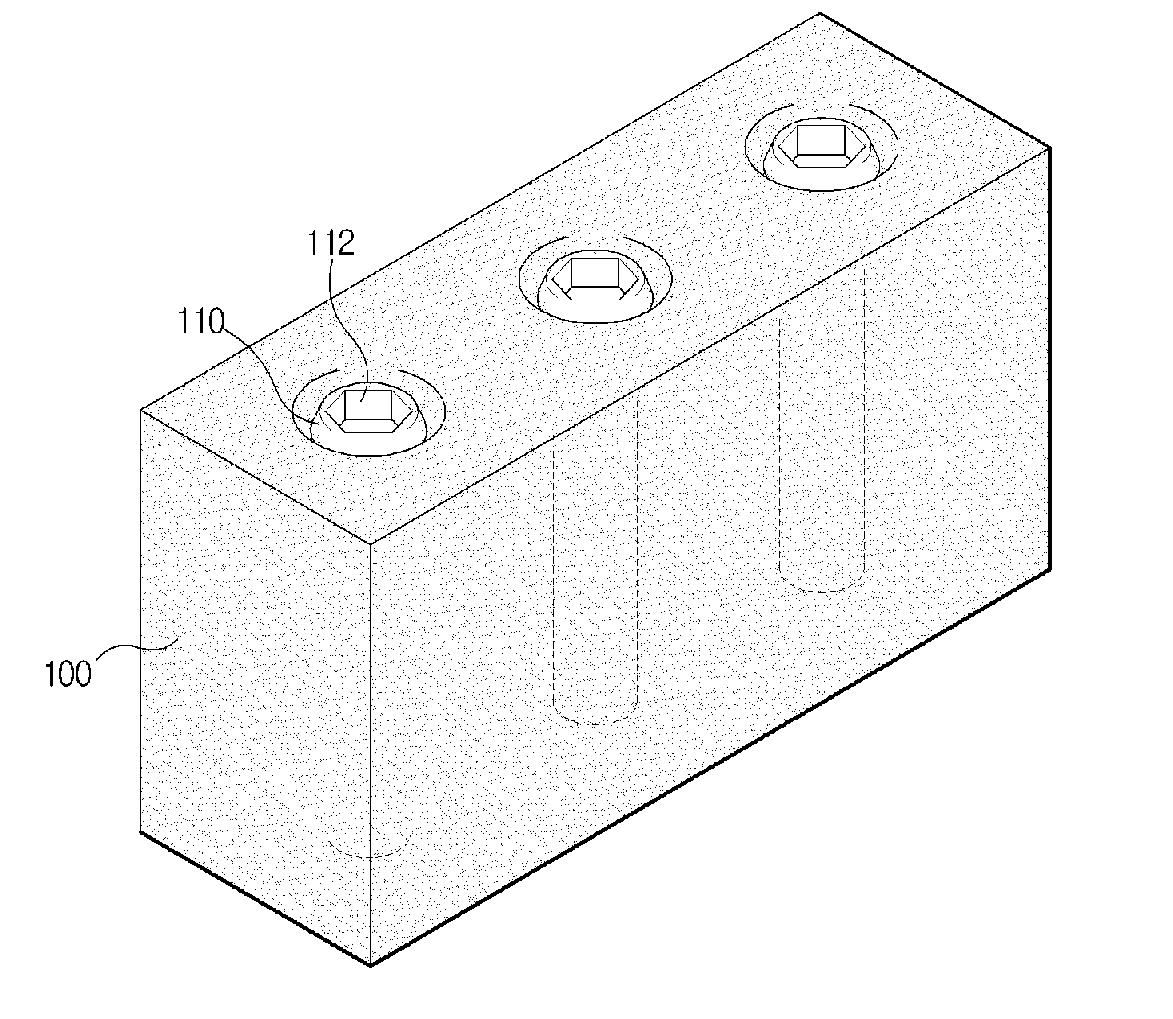
[0035]Thanks to the features of the block having a structure for joining an abutment and a superstructure for a dental implant and a method for manufacturing the same, advantages are provided in that a dental crown can be easily formed.

Problems solved by technology

However, if metal is used as the material of the abutment, when the thickness or the amount of surrounding soft tissues is small, disadvantages are caused in that the color of the metal is likely to be visible, or the surrounding tissues are perceived as gray, whereby a serious defect can result in the front teeth of the upper jaw, which play an important role from an aesthetical point of view.
While ceramic is also used as the material of the abutment in view of the excellent properties thereof so as to satisfy the aesthetic demands of some patients, problems arise in terms of working efficiency and the color of the teeth.
In particular, while, in actuality, ceramic products are made by only a few specialized bio ceramic companies having technical expertise, even in this case, a problem is caused in that the level of ceramic technology is insufficient, and thus they cannot be properly used in the art.
Therefore, in spite of the excellent properties of ceramic, it cannot be properly used as the material for the abutment due to the unsatisfactory state of ceramics technology and the inconvenience imposed on a patient.
Since the ready-made abutments as a whole have uniform shapes and should be re-shaped, or the shape thereof should be corrected to conform with the shapes of respective patients' teeth, the time required to manufacture dental prostheses is lengthened, and it is troublesome to implement the processes for manufacturing dental implants.

Method used


Image

  • Blocking Having Joining Structure of Dental Implant Abutment and Upper Structure and Manufacturing Method of the Same
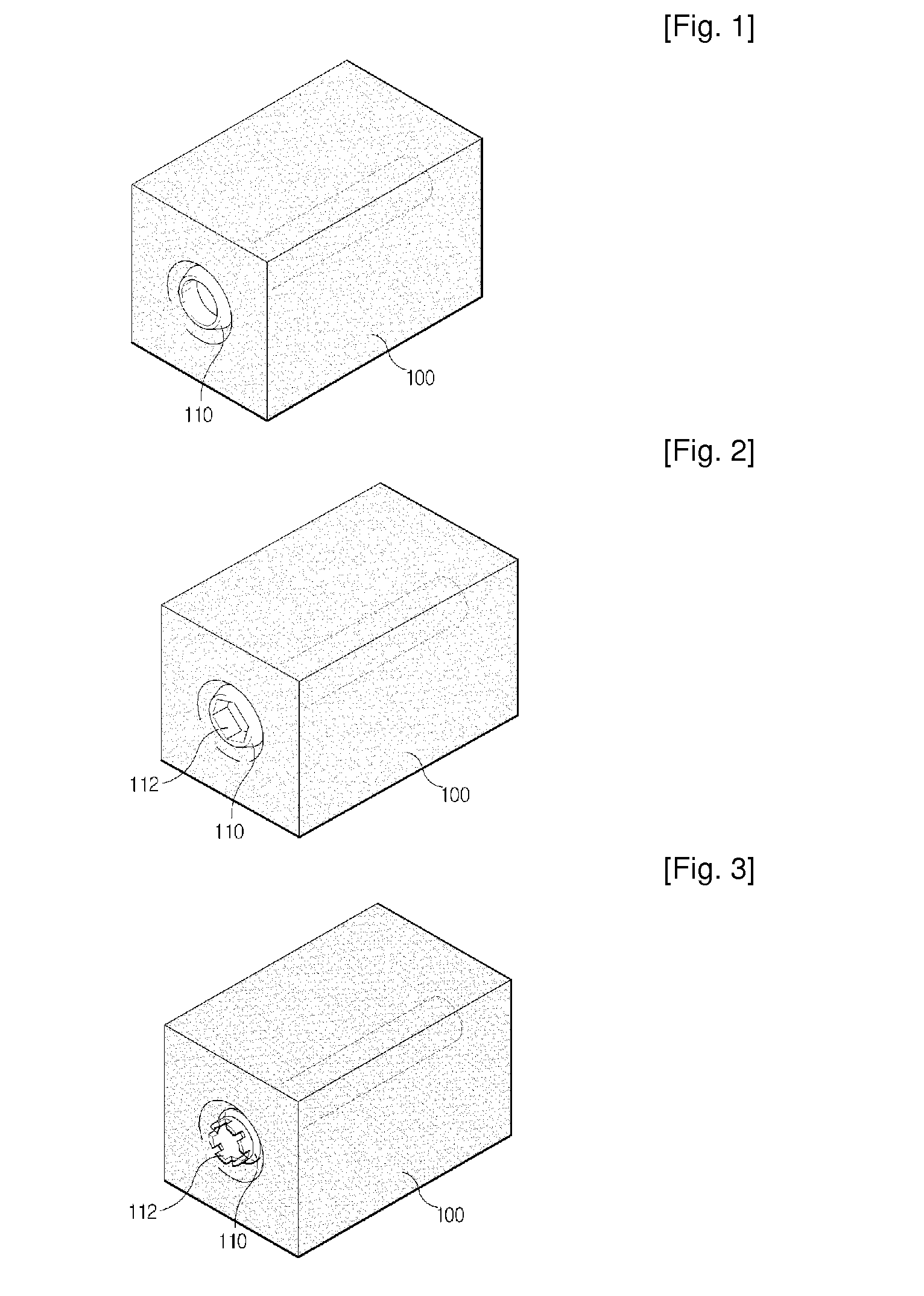
  • Blocking Having Joining Structure of Dental Implant Abutment and Upper Structure and Manufacturing Method of the Same
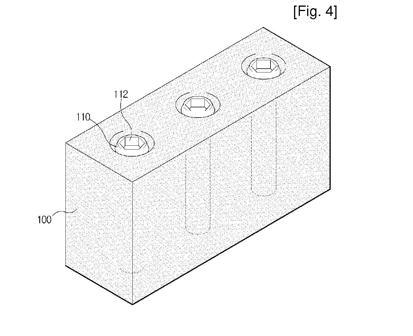
  • Blocking Having Joining Structure of Dental Implant Abutment and Upper Structure and Manufacturing Method of the Same

Examples


example 1

A Powder Forming Technique for Bidirectional Shrinkage Control

[0057]In the present example, a block is formed in a uniaxial die press having a maximum forming pressure of 20,000 psi and a cold isostatic press having a maximum pressure of 4,000 bar using materials having the compositions given in Table 1 under forming conditions set forth above. In uniaxial die pressing, a mold design for pressing and forming pressure were optimized, and tests for evaluating bidirectional shrinkage upon isostatic pressing were conducted for bidirectional shrinkage control (see Table 2 below).

TABLE 1The composition of materials of a block adopted for a dental implantClassificationCompositionZirconia97.0 mol % ZrO2, 3.0 mol % Y2O3Composite of zirconia / alumina10~90 vol % ZrO2, 90~10 vol % Al2O3

TABLE 2The condition for forming a block for a dental implantHolding timeand pressureBidirectionalProcessForming pressuredropshrinkage controlUniaxial dieOver formingOver 10PressingPressingstarting pointSecondsCol...

example 2

Techniques for Standardization of the Forming Condition of a Block by Primary Sintering and for the Evaluation of a Shrinkage Rate

[0059]In the present example, a technique for standardizing the forming condition of a block through pre-sintering was established. In detail, the blocks having undergone the uniaxial die pressing and the cold isostatic pressing were pre-sintered at various temperatures, and then, by examining the hardness and the density of the blocks, blocks suitable for machining were prepared. Further, by examining the forming shrinkage, attributable to the pressure of cold isostatic pressing (CIP), and pre-sintering shrinkage, a shrinkage evaluation technique was established. In order to improve machining efficiency, the blocks were sintered in a low-temperature sintering furnace while a primary sintering temperature was changed between 990° C. and 1,020° C., and the hardnesses of these pre-sintered products were measured in a micro Vickers hardness tester. Thereupon...

example 3

Reliability Evaluation of a Block

[0061]In order to check the long-term reliability of the method for manufacturing a block having a structure for joining an abutment and a superstructure for a dental implant, after conducting a bidirectional bending strength test, stability was observed through Weibull analysis. First, after preparing thirty Φ16*1.2 T disk pieces made of the same material as a block, the bidirectional bending strength tests were conducted using a universal material tester (Houns-field Test Equipment Ltd., U.K.), and the long-term stability was checked through the Weibull analysis for the measured strength values.

[0062]Here, a bidirectional bending strength value over 1,000 MPa, which represents an excellent property value, greater than 6,000 MPa, as the allowable strength value of the abutment for a dental implant, was obtained, and a Weibull coefficient m was 8.41, which means that the long-term stability could be confirmed.

[0063]Moreover, in the present invention,...


PUM


Abstract

Disclosed are a block having a structure for joining an abutment and a superstructure for a dental implant and a method for manufacturing the same. An abutment and a superstructure are not shaped in advance, and instead, a block, in which a structure for joining a fixture and other connection parts of a dental prosthesis are formed, is manufactured such that the block can be machined through CAD / CAM, or, after a wax mock-up or a resin mock-up is scanned and drawn on a paper, the block can be machined through CAM to form an abutment or the crown of a superstructure. In order to provide high strength and high toughness, the block is made of a stabilized tetragonal zirconia polycrystalline (TZP)-based material or a composite of zirconia and oxide. The method comprises the steps of pressing a starting material for a block, machining a resultant formation, and sintering the machined formation.

Description

TECHNICAL FIELD[0001]The present invention relates to a block having a structure for joining an abutment and a superstructure for a dental implant and a method for manufacturing the same, wherein, when manufacturing an abutment and a superstructure for a dental implant, the abutment and the superstructure are not shaped in advance, and instead, a block, in which a structure for joining a fixture and other connection parts of a dental prosthesis are formed, is manufactured such that the block can be machined through CAD / CAM, or, after a wax mock-up or a resin mock-up is scanned and drawn on paper, the block can be machined through CAM to form an abutment or the crown of a superstructure, and wherein, in order to provide high strength and high toughness, the block is made of a stabilized tetragonal zirconia polycrystalline (TZP)-based material or a composite of zirconia and oxide. To this end, the method for manufacturing a block having a structure for joining an abutment and a supers...

Claims


Application Information

Patent Timeline
IPC IPC(8): A61C8/00
CPCA61C8/005A61C13/0022A61C8/0051A61C8/00
Inventor KIM, DAE HYUN
Owner KIM EE
Learn More