
Power supply apparatus

a power supply and power supply technology, applied in the field of power supply apparatuses, can solve the problems of increasing the influence of noise generated by electric wires, increasing etc., and achieve the effects of suppressing an electric loss, ensuring safety, and reducing copper loss in the power supply apparatus

Inactive Publication Date: 2010-12-23
TOYOTA JIDOSHA KK +1
View PDF3 Cites 8 Cited by
  • Summary
  • Abstract
  • Description
  • Claims
  • Application Information

AI Technical Summary

Benefits of technology

[0007]The invention provides a power supply apparatus that further suppresses an electric loss and allows size reduction by more reliably electrically disconnecting two cells, from a plurality of cells that are connected in series to one another in an assembled battery.
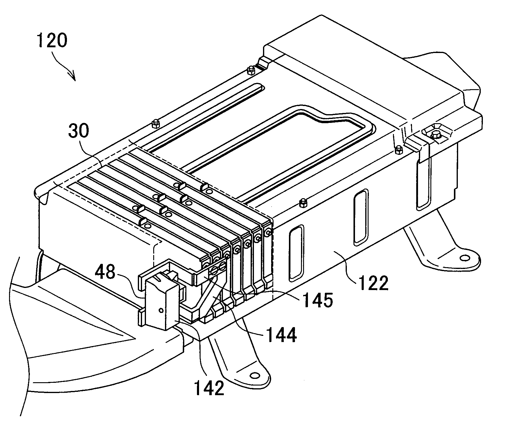
[0009]In the power supply apparatus, by removing the disconnection portion from the fixation portion, the predetermined two of the plurality of the cells may be more reliably electrically disconnected from each other. As a result, safety can be ensured during operation or inspection. Further, because the conductive plates of the fixation portion are directly connected to the two selected cells of the assembled battery respectively, the copper loss of the power supply apparatus can be reduced to further suppress an electric loss in comparison with a power supply apparatus having cells from which electric wires are drawn out. Because it is not necessary to provide space for the electric wires, the power supply apparatus can be reduced in size.

Problems solved by technology

Further, when the electric wire is drawn out from the power electric line, the copper loss in the power supply apparatus may be increased, and the influence of noise generated from the electric wire may be increased.

Method used


Image

  • Power supply apparatus
  • Power supply apparatus
  • Power supply apparatus

Examples


Embodiment Construction

[0017]FIG. 1 is a perspective view showing the structure of a power supply apparatus 20 according to the embodiment of the invention. FIG. 2 is a circuit diagram showing the electrical connection between an assembled battery 30 and a service plug 40 in the power supply apparatus 20 of FIG. 1. It should be noted in FIG. 1 that a case 22 and the assembled battery 30 inside the case 22 are indicated by broken lines and solid lines, respectively, as to a certain region (an upper right region in FIG. 1) of the power supply apparatus 20 to facilitate understanding of the invention. As shown in FIGS. 1 and 2, the power supply apparatus 20 according to the embodiment of the invention includes the assembled battery 30, the case 22, a cooling machine 26, and the service plug 40. The assembled battery 30 is composed of a plurality of cells 34 connected in series to one another. The case 22 accommodates the assembled battery 30. The cooling device 26 is attached to the case 22 to cool the assem...


PUM


Abstract

A power supply apparatus is equipped an assembled battery, a case that accommodates the assembled battery, and a connecting mechanism that is attached to an outside of the case, wherein the connecting mechanism connects two selected cells. The connecting mechanism includes a fixation portion and a disconnection portion. The fixation portion includes a first conductive plate that is directly connected to a positive electrode terminal of one of the two selected cells, and a second conductive plate that is directly connected to a negative electrode terminal of the other of the two selected cells, wherein the fixation portion is attached to the case. The disconnection portion is removable from the fixation portion, electrically connects the first conductive plate to the second conductive plate when attached to the fixation portion, and electrically disconnects the first conductive plate from the second conductive plate when removed from the fixation portion.

Description

INCORPORATION BY REFERENCE[0001]The disclosure of Japanese Patent Application No. 2009-148809 filed on Jun. 23, 2009, including the specification, drawings and abstract is incorporated herein by reference in its entirety.BACKGROUND OF THE INVENTION[0002]1. Field of the Invention[0003]The invention relates to a power supply apparatus.[0004]2. Description of the Related Art[0005]Japanese Patent Application Publication No. 9-265874 (JP-A-9-265874) describes a power supply apparatus that has an electric wire drawn out from a power electric line of a vehicle and an attachment body attached to a terminal end of the electric wire. In the described power supply apparatus, the power electric line of the vehicle may be electrically connected / disconnected by attaching / removing a conductor having a handle portion to / from the attachment body. Thus, during repair, inspection, or the like of the vehicle, safety may be ensured by electrically disconnecting the power electric line.[0006]However, in ...

Claims


Application Information

Patent Timeline
IPC IPC(8): H01M6/42H01H31/24H01M50/51
CPCH01M2/206H01M10/5067H01M10/5016H01M10/5004H01M10/625H01M10/6563H01M10/613Y02E60/10H01M50/51
Inventor KOSAKI, AKIHIROIIDA, KENJIIWABE, MASAAKIICHIKAWA, YOSHIAKIIKEDA, TOMOHIRO
Owner TOYOTA JIDOSHA KK
Learn More