
Transparent molded body and antireflective member using the same

a technology of anti-reflective parts and molded bodies, which is applied in the direction of identification means, instruments, other domestic objects, etc., can solve the problems of optical performance which cannot be reproduced by other methods, limitation of the reduction of reflectivity and dependence of reflectivity on wavelength, and difficulty in achieving the effect of good anti-fouling properties

Active Publication Date: 2010-12-23
MITSUBISHI CHEM CORP
View PDF0 Cites 31 Cited by
  • Summary
  • Abstract
  • Description
  • Claims
  • Application Information

AI Technical Summary

Benefits of technology

[0028]According to the present invention, it is possible to realize a transparent molded body, in which an active energy ray-curable resin having an uneven structure with a good antifouling property and scratch resistance is formed on the surface.

Problems solved by technology

Interfaces (surfaces) that come in contact with air, such as a variety of displays, lenses, show windows, and the like suffer a problem of reduced visibility due to the reflection of solar light, lighting, or the like on their surfaces.
However, in these methods, there is a limitation on the reduction in the reflectivity and the dependency of the reflectivity on the wavelength even when the number of laminated films is increased.
Also, the antireflective film exhibits excellent optical performances which cannot be reproduced by other methods.
However, the active energy ray-curable resin as described in Patent Document 1 is not hydrophilic, and thus, it has a water contact angle of more than 25°, and as a result, it does not exhibit the antifouling property.
Further, if the surface energy is reduced as described in Patent Documents 2 and 3, little soiling substance adheres, but the soil is caught in the concave portion, and thus, there was a problem that once the soiling substance is embedded, it is hard to remove in use.
In addition, as described in Patent Document 4, in the case of using a photocatalyst, it was difficult for the decomposition of dust to proceed indoors.
Also, if a resin film or the like was used as a base and its surface was coated with a photocatalyst layer, there were problems such as the decomposition of even the resin film.
Moreover, with the antifouling article having a fine uneven structure obtained by the preparation method as described in Patent Documents 5 and 6, there were problems in that it was difficult to control the distance between the adjacent convex portions or the height of the convex portion, and that the antireflective property could not be sufficiently obtained.
Furthermore, even though the method as described in Patent Document 7 was applied to a fine uneven structure, there was a problem in that the antifouling property is not sufficiently enforced.

Method used


Image

  • Transparent molded body and antireflective member using the same
  • Transparent molded body and antireflective member using the same

Examples


example 1

Preparation of Transparent Molded Body

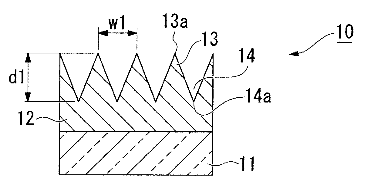
[0095]1.5 parts by weight of Irgacure 184 (manufactured by Ciba Specialty Chemicals Inc.) based on 100 parts by weight of the monomers was dissolved in 20 parts by weight of dipentaerythritol hexaacrylate (DPHA), 70 parts by weight of Aronix M-260 (manufactured by Toagosei Co., Ltd.; the number of the average repeating units of the polyethylene glycol chain: 13), and 10 parts by weight of hydroxyethyl acrylate, thereby obtaining an active energy ray-curable composition. A few drops of the active energy ray-curable composition were dropped on a stamper and coated by spreading on an acryl resin film, and then by the active energy ray-curable composition being photocured by irradiation with an ultraviolet ray at an energy level of 400 mJ / cm2 from the side of the film. The film and the stamper were released to obtain a transparent molded body having a fine uneven structure with a distance w1 between the adjacent convex portions of 200 nm and a heigh...

example 2

[0099]In the same manner as in Example 1, except that 30 parts by weight of dipentaerythritol hexaacrylate (DPHA) and 60 parts by weight of Aronix M-260 (manufactured by Toagosei Co., Ltd.) were used, a transparent molded body having a fine uneven structure with a distance w1 between the adjacent convex portions of 200 nm and a height of the convex portion d1 of 200 nm was prepared, and evaluations of the water contact angle, the antifouling property test, and the reflectivity were carried out. The results are shown in Table 1.

example 3

[0100]In the same manner as in Example 1, except that 40 parts by weight of dipentaerythritol hexaacrylate (DPHA) and 50 parts by weight of Aronix M-260 (manufactured by Toagosei Co., Ltd.) were used, a transparent molded body having a fine uneven structure with a distance w1 between the adjacent convex portions of 200 nm and a height of the convex portion d1 of 200 nm was prepared, and evaluations of the water contact angle, the antifouling property test, and the reflectivity were carried out. The results are shown in Table 1.


PUM

PropertyMeasurementUnit
water contact angleaaaaaaaaaa
distance w1aaaaaaaaaa
wavelengthaaaaaaaaaa

Abstract

The present transparent molded body is a transparent molded body including a transparent substrate and an uneven layer composed of a cured product of an active energy ray-curable composition formed on at least one surface of the transparent substrate, wherein the uneven layer has an uneven structure having a gap between the adjacent convex portions equal to or less than the wavelength of a visible light, the water contact angle of the surface of the uneven layer is equal to or less than 25°, and the modulus of elasticity of the surface of the uneven layer is equal to or more than 200 MPa.

Description

TECHNICAL FIELD[0001]The present invention relates to a transparent molded body and an antireflective member using the same.[0002]The present invention claims priority benefit based on Japanese Patent Application No. 2007-30277 filed on Feb. 9, 2007, the content of which is incorporated herein by reference in its entirety.BACKGROUND ART[0003]Interfaces (surfaces) that come in contact with air, such as a variety of displays, lenses, show windows, and the like suffer a problem of reduced visibility due to the reflection of solar light, lighting, or the like on their surfaces. As a method for reducing the reflection, a method for laminating several layers of films having different refractive indices so as to match and cancel by interference the reflected light on the film surface and the reflected light at the interface between the film and the base. These films are usually prepared by a method such as sputtering, evaporation, coating, and the like. However, in these methods, there is ...

Claims


Application Information

Patent Timeline
Patent Type & Authority Applications(United States)
IPC IPC(8): G02B1/11B32B3/30B32B27/32C08F290/06G02B1/111G09F9/00
CPCG02B1/118G02B27/0006Y10T428/24355Y10T428/2457Y10T428/24612Y10S428/913G02B1/10G02B1/11G09F9/00B05D3/067B08B17/06
Inventor SAKUMA, SATOSHIOKAMOTO, EIKOUOZU, YOSHIHIRO
Owner MITSUBISHI CHEM CORP
Learn More