
Vacuum and positive pressure ventilation systems and methods for intrathoracic pressure regulation

Active Publication Date: 2010-12-23
ZOLL MEDICAL CORPORATION
View PDF71 Cites 148 Cited by
  • Summary
  • Abstract
  • Description
  • Claims
  • Application Information

AI Technical Summary

Benefits of technology

[0047]Exemplary systems may include a processor, and a memory coupled with the processor. The memory may include a positive pressure ventilation code module comprising instructions for operating the positive pressure ventilation mechanism, and a respiratory extraction code module comprising instructions for operating the respiratory extraction mechanism. In some cases, a treatment system includes a circuit having two limbs, a manifold that maintains separation between inspiratory gases and expiratory gases, and a removable protective case that is resistant to impact and moisture. Treatment systems may also include a sensor assembly that facilitates breath control. What is more, treatment systems may include a blower mechanism that facilitates control of expiratory resistance. Optionally, systems can be configured so that a blower mechanism operates based on a feedback control loop.

Problems solved by technology

This results in the rapid displacement of blood within the lungs into the left atrium, thereby priming the left heart with blood.
This results in a ‘wringing out’ of the lungs much like a wet sponge with each application of the vacuum and this forces the blood in the lungs into the left heart as the pulmonic valve prevent reverse transpulmonary flow.

Method used


Image

  • Vacuum and positive pressure ventilation systems and methods for intrathoracic pressure regulation
  • Vacuum and positive pressure ventilation systems and methods for intrathoracic pressure regulation
  • Vacuum and positive pressure ventilation systems and methods for intrathoracic pressure regulation

Examples


example 1

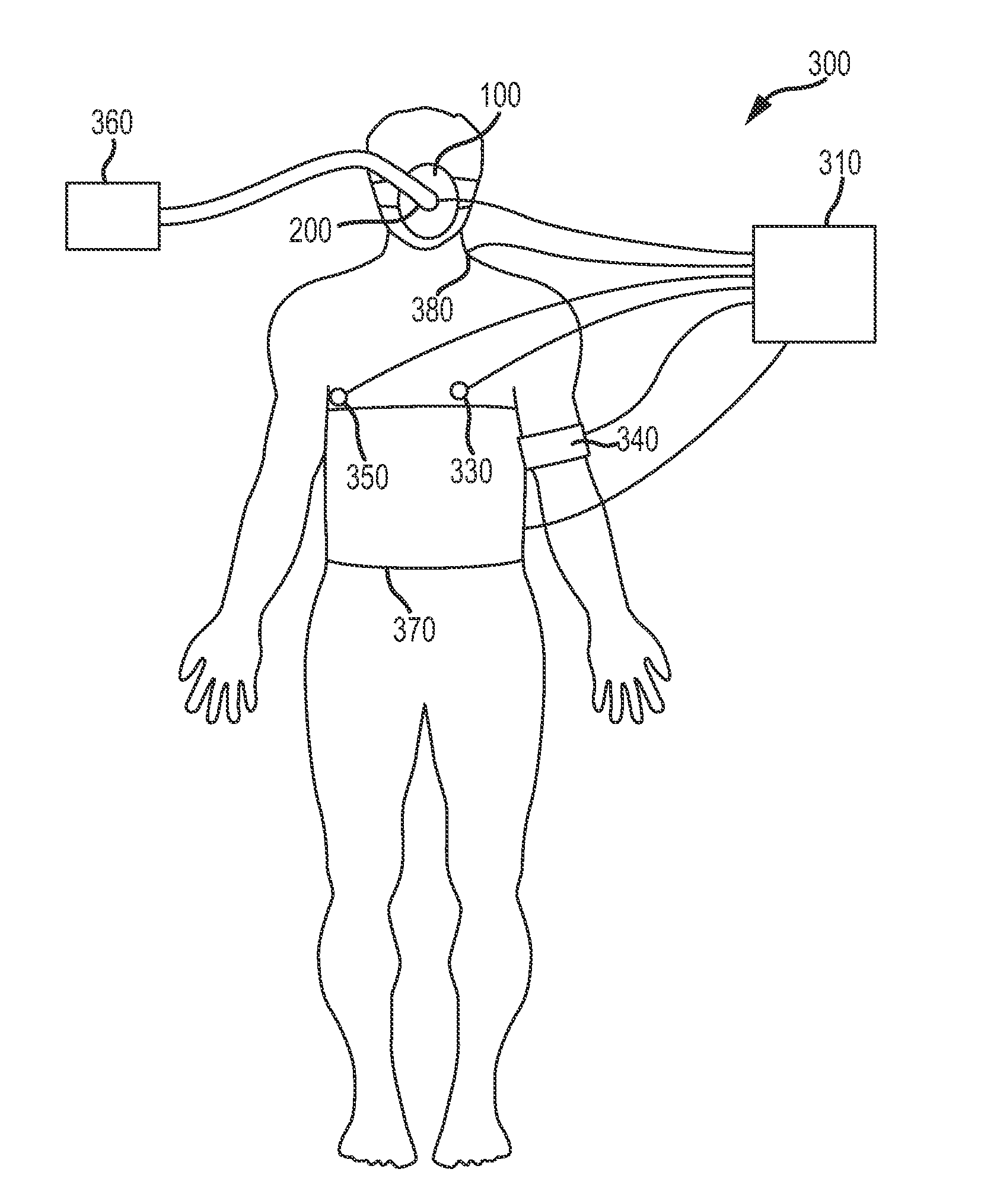
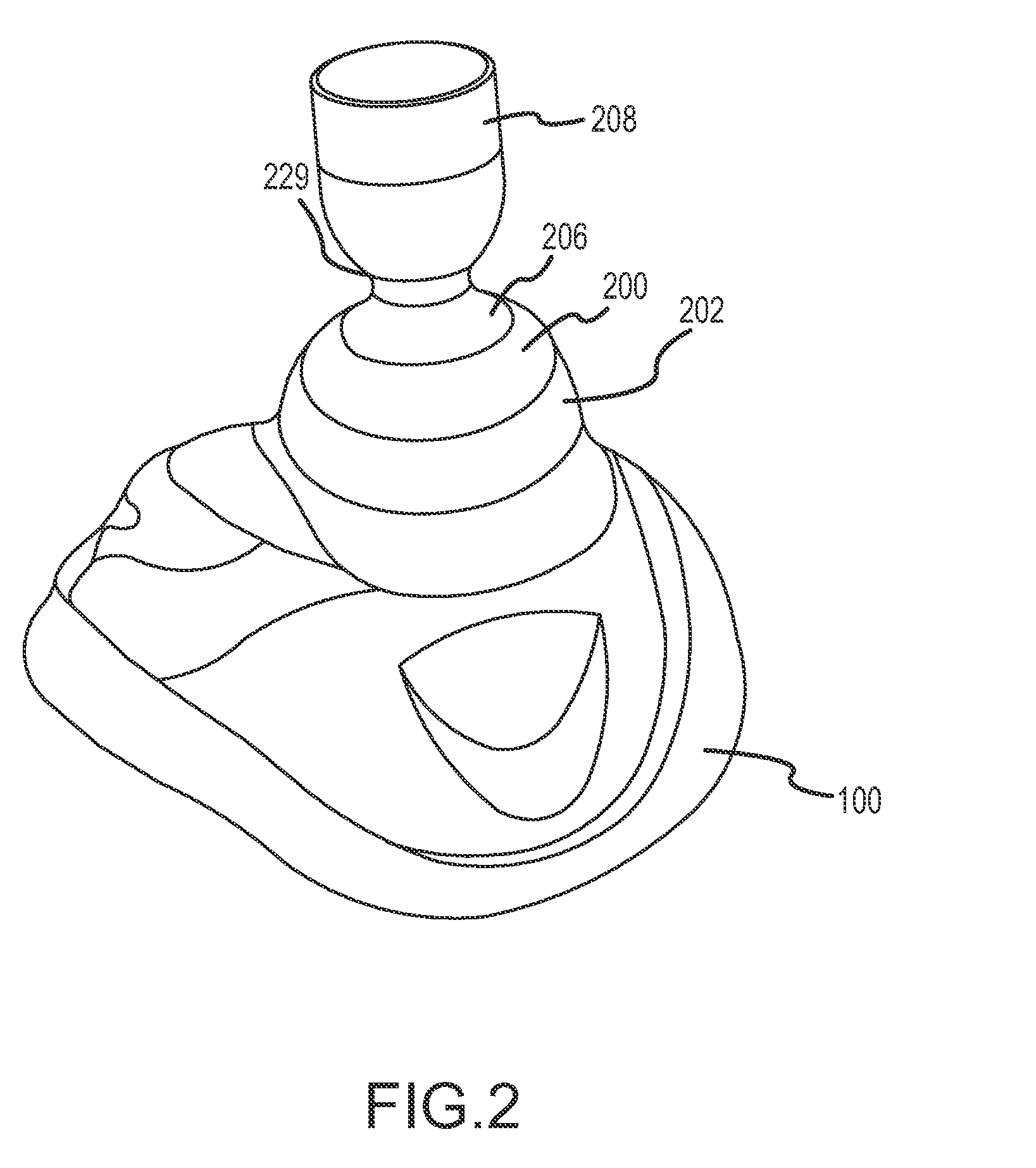
[0104]The following is a non-limiting example illustrating how intracranial pressures may be lowered according to the invention. In this example, 30 kg pigs were anesthetized with propofol. Using a micromanometer-tipped electronic Millar catheter inserted below the dura, intracranial pressures were measured continuously in the spontaneously breathing pigs. Intrathoracic pressures (ITP) were recorded using a Millar catheter placed in the trachea at the level of the carina. After stabilizing the pigs blood pressure, heart rate, and ventilation rate, intracranial pressures (ICP) and intrathoracic pressures were recorded, with 0 cm H2O inspiratory impedance and then with inspiratory impedances of 5, 10, 15, and 20 cm H2O. Inspiratory impedance was achieved using an impedance threshold valve (ITV) as described in FIGS. 2-5.

[0105]At base, the intracranial pressure was approximately 8 / 4 mmHg. With increasing amounts of inspiratory impedance, the intracranial pressure was lowered proportion...

example 2

[0106]In this example, intracranial pressures were increased in the setting of recovery from cardiac arrest. The example used a pig model with ventricular fibrillation for 6 minutes followed by cardiopulmonary resuscitation for 6 minutes, followed by defibrillation. Spontaneous breathing resulted in an up to 50% decrease in intracranial pressures when the animals breathed through an inspiratory impedance of 10 cm H2O using a valve system similar to Example 1.

[0107]In all examples above, the intrathoracic pressure decreased relative to the rest of the body, creating a suction effect that reduced the pressure in the venous blood vessels draining the brain, thereby reducing intracranial pressures.

[0108]The invention further provides techniques and devices for reducing intracranial pressure (ICP) by facilitating movement of cerebral spinal fluid (CFS). There are a number of causes of increased ICP including: head injury, ischemia, osmolar imbalance, cerebral edema, tumors, complications...

example 3

[0134]Example 3 is another non-limiting example illustrating how intracranial pressures and intrathoracic pressures may be lowered and systolic arterial pressure may be increased according to one aspect of the invention. In this example, 30 kg pigs were anesthetized with propofol. Using a micromanometer-tipped electronic Millar catheter inserted 2 cm below the dura, intracranial pressures were measured in non-breathing pigs. Intrathoracic pressures (ITP) were recorded using a Millar catheter placed in the trachea at the level of the carina. Systolic aortic blood pressures (SBP) were measured in the aorta with a Millar catheter. To regulate intrathoracic pressures, a system similar to that illustrated in FIGS. 14A, 14B, 15A and 15B was used, with inspiratory impedance (−8 cm H2O with a flow rate of 30 L / min). Positive pressure ventilation was provided at a rate of 10 breaths / min with a tidal volume of approximately 400 ml delivered over 1.0 seconds with an automatic transport ventila...


PUM


Abstract

Medical techniques include systems and methods for administering a positive pressure ventilation, a positive end expiratory pressure, and a vacuum to a person. Approaches also include treating a person with an intrathoracic pressure regulator so as to modulate or upregulate the autonomic system of the person, and treating a person with a combination of an intrathoracic pressure regulation treatment and an intra-aortic balloon pump treatment.

Description

CROSS-REFERENCES TO RELATED APPLICATIONS[0001]This application is a nonprovisional of, and claims the benefit of the filing date of, U.S. Provisional Patent Application No. 61 / 218,763 filed Jun. 19, 2009 (Attorney Docket No. 016354-006800US). This application is also related to U.S. patent application Ser. No. 11 / 034,996 filed Jan. 12, 2005 (Attorney Docket No. 016354-005214US), which is a continuation in part of U.S. patent application Ser. No. 10 / 796,875 filed Mar. 8, 2004 (Attorney Docket No. 016354-005213US) and a continuation in part of U.S. patent application Ser. No. 10 / 660,462 filed Sep. 1, 2003 (U.S. Pat. No. 7,082,945; Attorney Docket No. 016354-005211US), which is a continuation in part of U.S. patent application Ser. No. 10 / 460,558 filed Jun. 11, 2003 (U.S. Pat. No. 7,185,649; Attorney Docket No. 016354-005210US), which is a continuation in part of U.S. patent application Ser. No. 10 / 426,161 filed Apr. 28, 2003 (U.S. Pat. No. 7,195,012; Attorney Docket No. 016354-005200U...

Claims


Application Information

Patent Timeline
IPC IPC(8): A61M16/20A61M16/10A61M16/06A61M16/08
CPCA61M2016/0027A61M16/202A61M2205/3331A61M2205/3553A61M2205/3584A61M2205/50A61M2205/502A61M2205/505A61M2230/06A61M2230/205A61M2230/208A61M2230/30A61M2230/42A61M2230/432A61M2230/50A61N1/39A61H31/02A61H2230/06A61H2230/30A61H2230/40A61M16/00A61M16/0051A61M16/0078A61M16/009A61M16/06A61M16/12A61M16/20A61M16/208A61N1/3601A61M16/0825A61M16/0009A61M2016/0036A61M16/0833A61M16/0012A61M16/1065A61M2016/102A61M16/085A61M16/0858A61M16/205A61M16/024A61N1/39044A61M16/0003A61M16/201A61M16/0057A61M16/04A61M2205/3334
Inventor LURIE, KEITHMETZGER, ANJAKRUEGER, KURTVOSS, GREG
Owner ZOLL MEDICAL CORPORATION
Learn More