
Distance-to-fault measurement system capable of measuring complex reflection coefficients

a technology of distance-to-fault measurement and reflection coefficient, which is applied in the direction of pulse reflection method, resistance/reactance/impedence, instruments, etc., can solve the problems of reducing the performance of the communication system, and affecting the reliability of the transmission system

Active Publication Date: 2010-12-09
BAE SYST INFORMATION & ELECTRONICS SYST INTERGRATION INC
View PDF29 Cites 23 Cited by
  • Summary
  • Abstract
  • Description
  • Claims
  • Application Information

AI Technical Summary

Benefits of technology

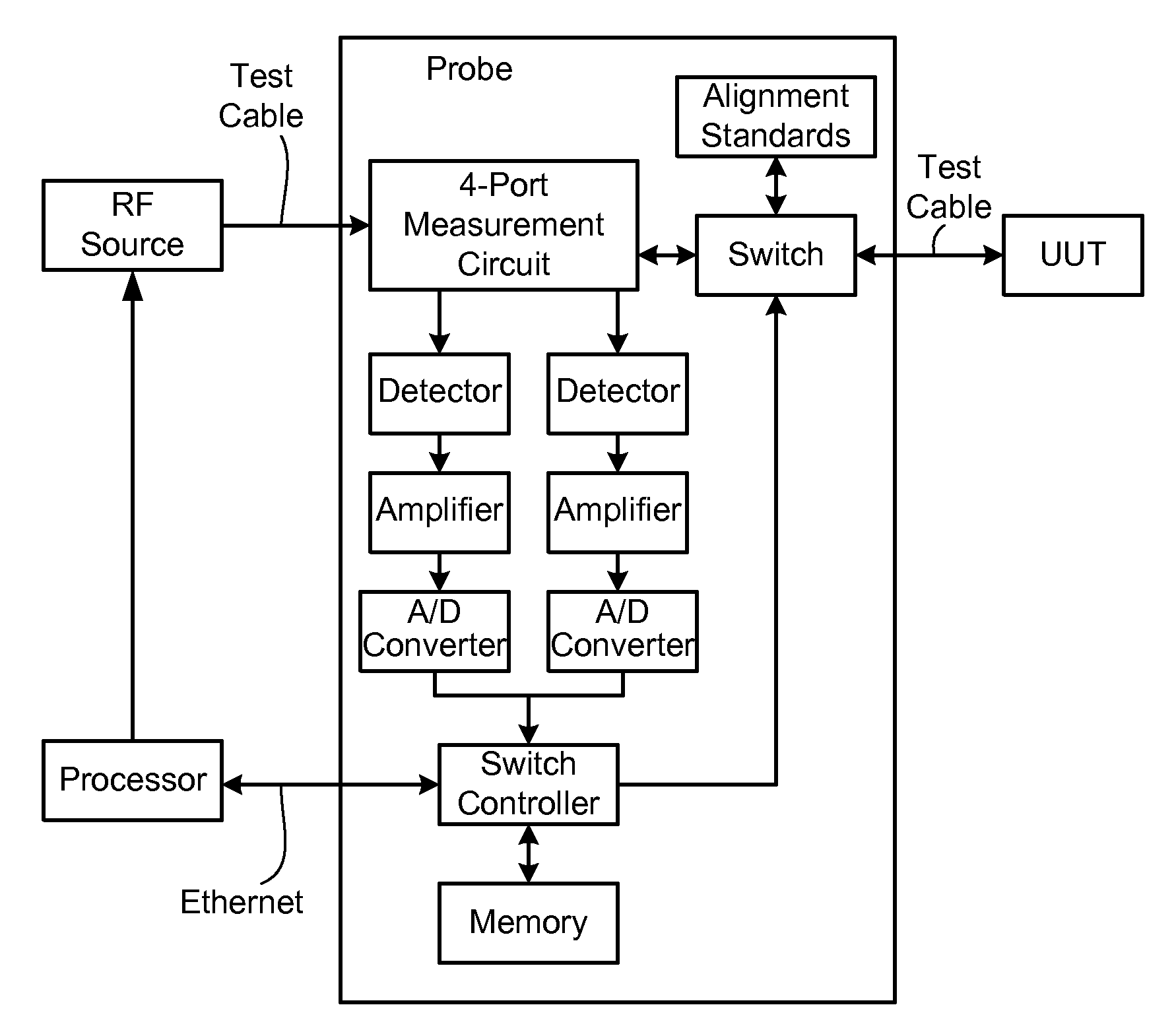
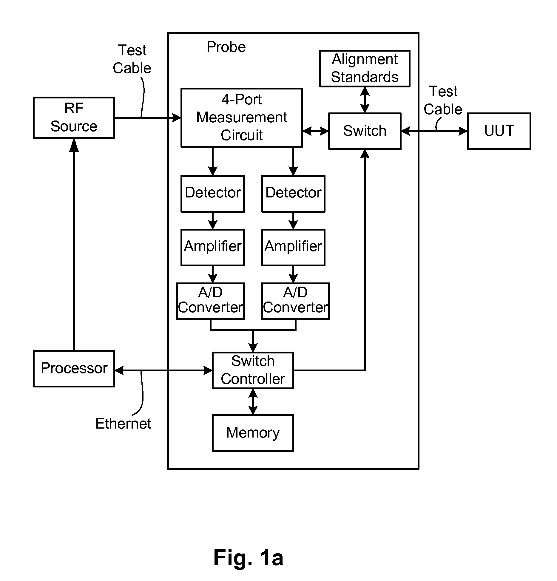
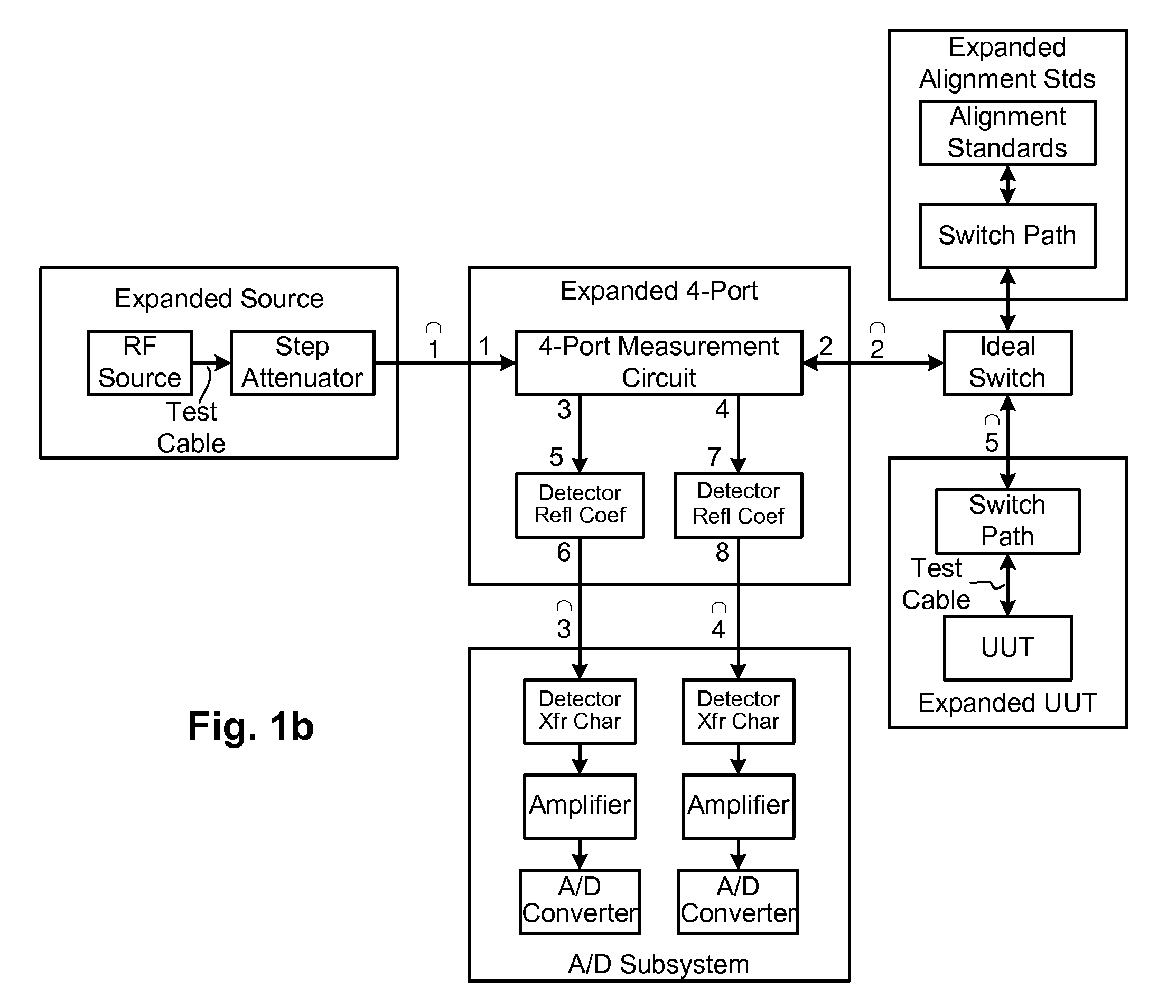
[0006]One embodiment of the present invention provides a method for computing a complex reflection coefficient of a unit under test (UUT) with a distance to fault (DTF) system having a probe that is operatively coupled to the UUT. The method includes performing probe alignment to produce measured alignment voltages, and adjusting calibration values based on the measured alignment voltages to produce adjusted calibration values. The method continues with measuring UUT voltages with the probe to produce measured UUT voltages, and computing a complex reflection coefficient of the UUT using the measured UUT voltages and the adjusted calibration values. The complex reflection coefficient is computed as a function of known scattering parameters of a multi-port measurement circuit included in the probe. The method may include the preliminary steps of displaying a graphical user interface (GUI) on a display viewable by a user, thereby allowing a user to select desired test parameters of the DTF system, and modifying test parameters of the DTF system based on the user selections. The method may include displaying the computed complex reflection coefficient (e.g., graphically over a range of frequencies, or as one or more discrete values at corresponding frequencies). In one particular case, the scattering parameters of the multi-port measurement circuit are mathematically represented as a 4 by 4 scattering matrix that takes into account detectors included in the probe. In one such case, the 4 by 4 scattering matrix completely specifies transfer functions of the probe's multi-port measurement circuit, and is used in mathematically representing the DTF system and UUT to be: an expanded multi-port measurement circuit (as a function of the complex reflection coefficients of the detectors included in the probe); an expanded source (as a function of an RF source attenuator setting); and an expanded UUT (as a function of switch paths and alignment standards). In one particular case, performing probe alignment to produce measured alignme...

Problems solved by technology

In short, such impairments can cause unwanted signal reflections, which in turn diminish the performance of the communication system.
Unfortunately, vector network analyzers tend to be expensive and are generally bulky and heavy.

Method used


Image

  • Distance-to-fault measurement system capable of measuring complex reflection coefficients
  • Distance-to-fault measurement system capable of measuring complex reflection coefficients
  • Distance-to-fault measurement system capable of measuring complex reflection coefficients

Examples


Embodiment Construction

[0021]Techniques are disclosed for computing distance-to-fault (DTF) in communication systems. The techniques can be embodied, for instance, in a DTF system that provides a multi-port probing device and DTF functionality, including computing distances to faults and the fault magnitudes. In addition, the DTF system is further configured with the ability to accurately measure complex reflection coefficients of the UUT, and / or return loss of the UUT. As is known, the return loss of the UUT is easily computed from the complex reflection coefficient (i.e., Return loss=1−Ireflection coefficient).

General Overview

[0022]In order to allow the DTF system to accurately measure the complex reflection coefficient of the multi-port probing device, the system is programmed or otherwise configured to take into account various probe scattering parameters (s-parameters) that are ignored by conventional DTF systems. In particular, such conventional systems approximate these s-parameters as being of zer...


PUM


Abstract

Techniques are disclosed for computing distance-to-fault (DTF) in communication systems. The techniques can be embodied, for instance, in a DTF system that provides a multi-port probing device and DTF functionality, including computing distances to faults and the fault magnitudes. In addition, the DTF system is further configured with the ability to accurately measure complex reflection coefficient of the UUT, and / or return loss of the UUT. The complex reflection coefficient and / or return loss of the UUT can be computed as a function of known scattering parameters of a multi-port measurement circuit included in the probe of the DTF system.

Description

RELATED APPLICATIONS[0001]This application is related to U.S. Pat. Nos. 7,061,221, 7,061,251, 7,171,322, and 7,254,511, each of which is herein incorporated by reference in its entirety.FIELD OF THE INVENTION[0002]The invention relates to techniques for measuring complex reflection coefficients of single-port radio frequency (RF) and microwave devices, and more particularly, to techniques for improving distance-to-fault (DTF) measurement systems to accurately measure complex reflection coefficients of single-port devices.BACKGROUND OF THE INVENTION[0003]Distance-to-fault (DTF) generally refers to analyzing the performance of a communication medium, such as a transmission line or antenna. DTF typically employs time domain reflectometry (TDR) or frequency domain reflectometry (FDR), which allows for fault isolation in a transmission system by identifying the presence and location of signal path impairment (e.g., damaged transmission line or connector, loose connection, faulty componen...

Claims


Application Information

Patent Timeline
IPC IPC(8): G01R31/08G06F19/00
CPCG01R27/04G01R31/11G01R31/2822
Inventor TAYLOR, MATTHEW A.
Owner BAE SYST INFORMATION & ELECTRONICS SYST INTERGRATION INC
Learn More