Arrangement and method for measuring relative movement

a technology of relative movement and arrangement, applied in the direction of measuring devices, instruments, using optical means, etc., can solve the problems of high manufacturing cost, difficult adjustment of reference mirrors, and sensitive michelson interferometers, so as to achieve low manufacturing cost, easy adjustment of optical components, and large tolerances of optical components

Active Publication Date: 2010-12-09
GASERA
View PDF9 Cites 2 Cited by
  • Summary
  • Abstract
  • Description
  • Claims
  • Application Information

AI Technical Summary

Benefits of technology

[0038]An advantage of the invention is that an amplitude splitting beamsplitter is not needed in measuring small movements. In the measuring arrangement according to the invention the wavefront of the light beam is splitted into wavefront portions whereas in the prior art systems based on Michelson interferometers the amplitude of the light beam is divided.
[0039]Another advantage of the invention is that large tolerances of optical components are acceptable and the need for adjustment of optical components is minimal. Loose tolerance requirements of optical components allow mass production without alignment procedure in a manufacturing process. Also the components of the measuring arrangement are inexpensive to manufacture.
[0040]Still another advantage is that because the moving element and the reference element are close to each other and are thus susceptible to similar temperatures, the arrangement according to the invention is not sensitive to temperature variations. Also, due to the structure of the measuring arrangement the distance between the elements and the other optical components can be easily increased whereupon the moving element and the reference element can be positioned in a temperature and / or pressure which would be unsuitable for the other optical components of the measuring arrangement. The distance between the elements and the other optical components can be increased with minimal changes to the structure. However, in a Michelson interferometer, if the distance between a moving mirror and a beamsplitter is increased the optical path length in another interferometer arm must also be increased which increases the size of the interferometer.
[0041]The moving element and the reference element can be positioned inside a measuring chamber having a window. An advantage is that the light going to and reflecting from the moving element, and the light going to and reflecting from the reference element go through the same window. In the prior art systems based on Michelson interferometers, only the sensor is positioned inside a chamber behind a window. The addition of the window between a beamsplitter and the sensor decreases the performance of the interferometer.
[0042]Still another advantage is that with the present invention high measurement precision and wide linear dynamic range can be achieved.
[0043]The measuring arrangement according to the invention can be utilised in e.g. pressure sensors, temperature sensors, thermal energy sensors, calorimetry, radiation sensors, atomic force microscopy, photoacoustic sensors for solid, liquid and gas samples, accelerometers, vibration sensors, microphones and small mass measurements.

Problems solved by technology

The Michelson interferometer is quite sensitive to temperature variations, mainly because the sensor and the reference mirror are situated apart from each other in different interferometer arms, and are thus susceptible to temperature changes between the arms.
It is also a disadvantage that the reference mirror must be precisely adjusted in order to obtain accurate measurements of the movement of the sensor.
A further disadvantage is that the optical components in the Michelson interferometer must be of a high quality and are thus expensive to manufacture, especially the amplitude splitting beamsplitter.

Method used


Image

  • Arrangement and method for measuring relative movement
  • Arrangement and method for measuring relative movement
  • Arrangement and method for measuring relative movement

Examples


first embodiment

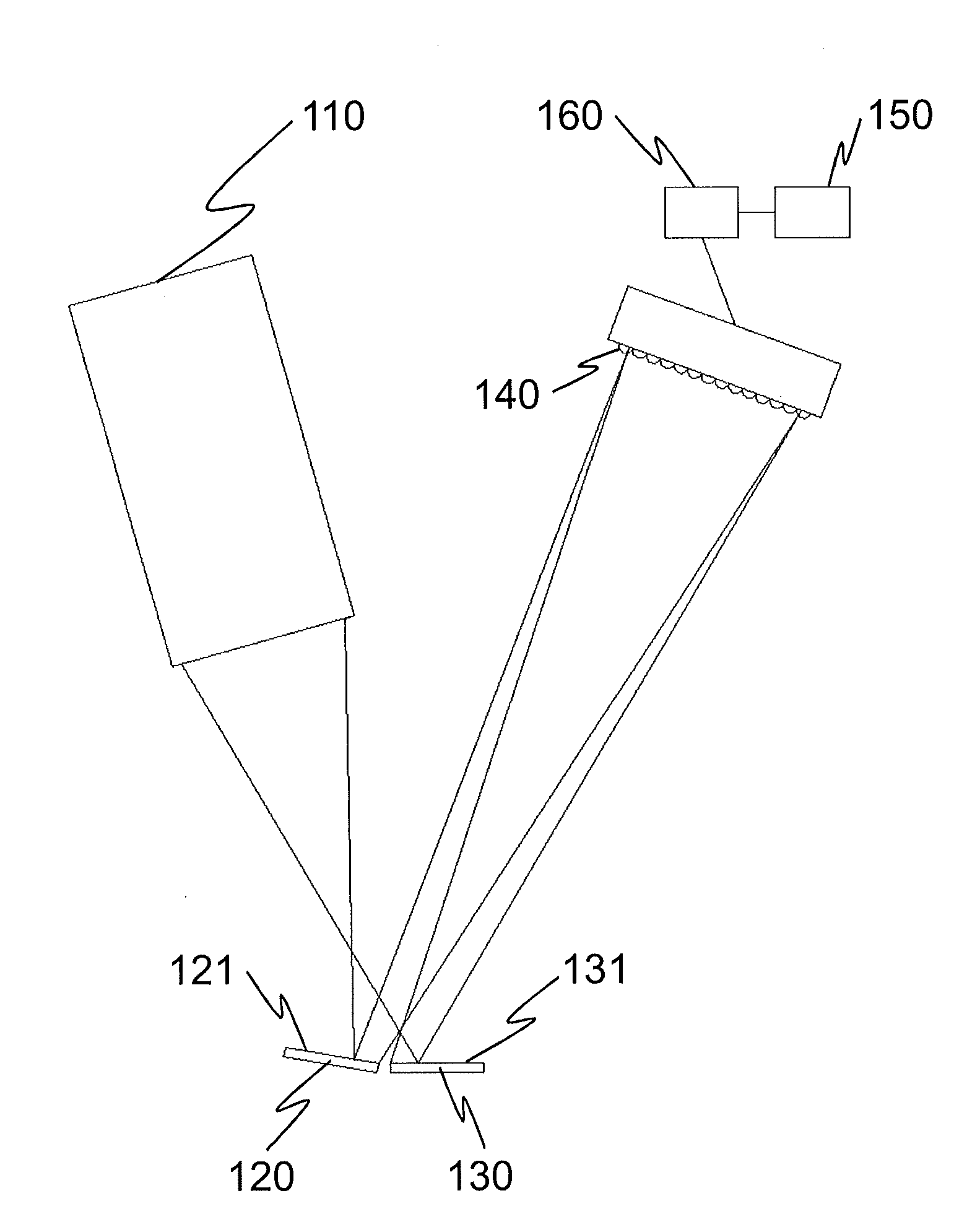
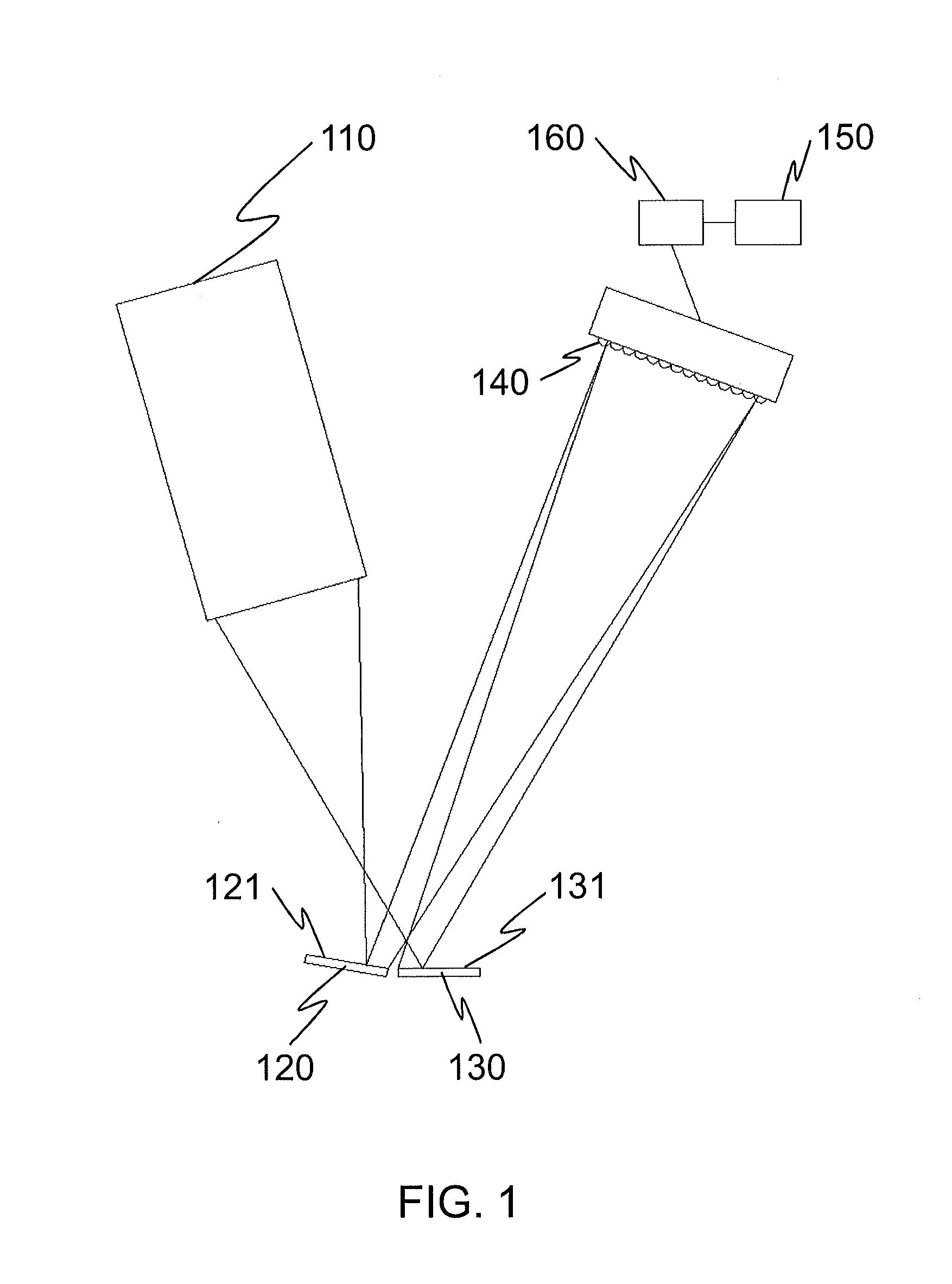
[0046]FIG. 1 illustrates schematically an arrangement according to the invention, and

second embodiment

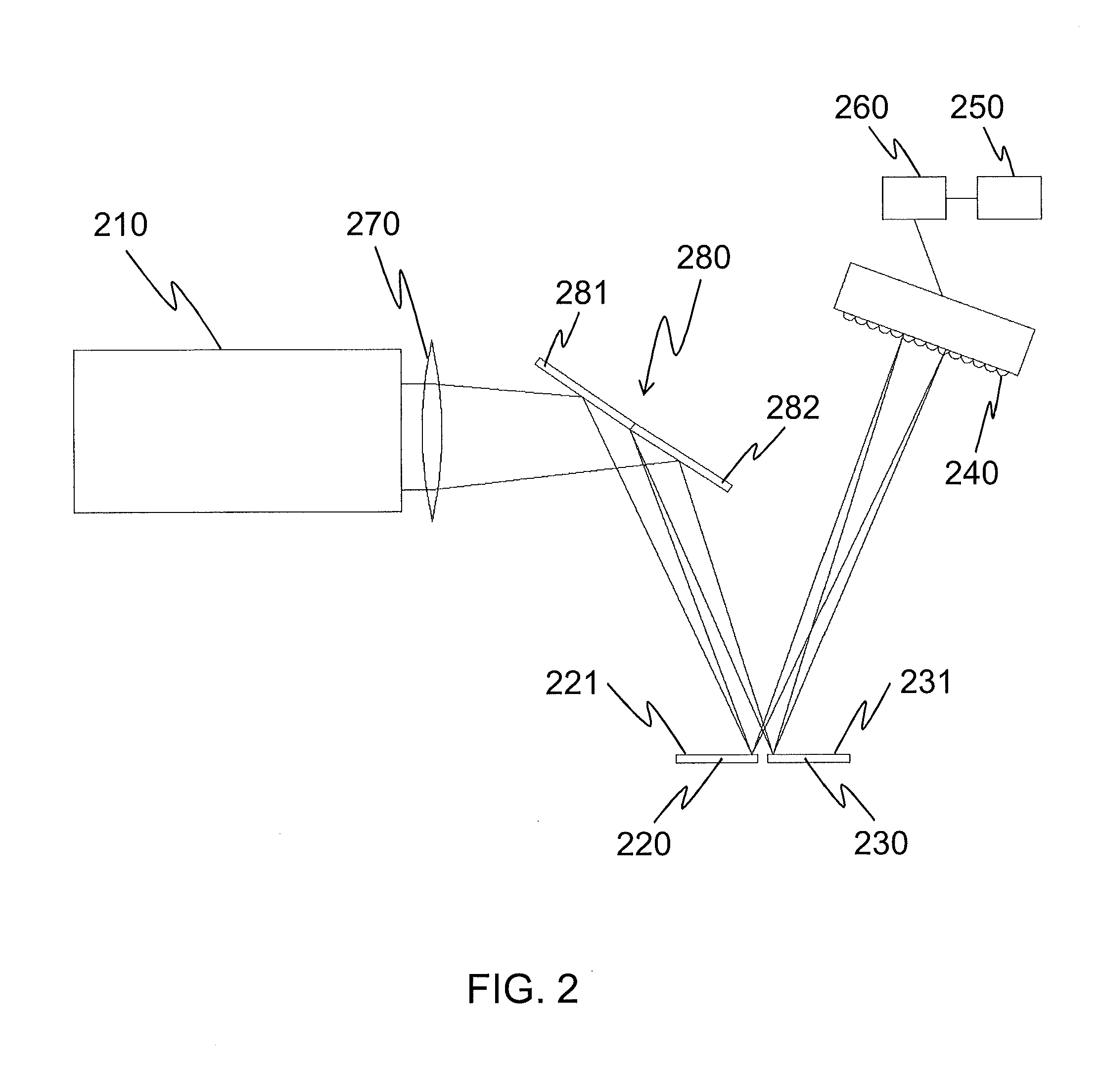
[0047]FIG. 2 illustrates schematically an arrangement according to the invention.

DETAILED DESCRIPTION OF THE PREFERRED EMBODIMENTS OF THE INVENTION

[0048]FIG. 1 illustrates an arrangement according to a first embodiment of the invention for measuring relative movement. The arrangement comprises a laser 110 as a light source. The laser 110 emits a light beam towards a moving element 120 and a reference element 130 which both have a reflective surface 121, 131. The light beam is directed to the moving element 120 and the reference element 130 as an undivided wavefront. The focus of the light beam is arranged in front of the moving element 120 and the reference element 130, i.e. the focus of the light beam is between the laser 110 and said elements 120, 130.

[0049]The wavefront splitting is performed by the moving element 120 and the reference element 130. The reflective surface 121 of the moving element 120 reflects a first wavefront portion of the light beam, and the reflective surface...


PUM


Abstract

The present invention relates to an arrangement for measuring relative movement. The measuring arrangement comprises a light source (110, 210) for emitting a light beam, a moving element (120, 220) having a reflective surface (121, 221) adapted to reflect a first wavefront portion of the light beam, and a reference element (130, 230) having a reflective surface (131, 231) adapted to reflect a second wavefront portion of the light beam. The arrangement further comprises detecting means (140, 240) for detecting changes in a spatial interference pattern produced by the light reflected from the moving element and the reference element, and processing means (150, 160, 250, 260) for calculating the relative movement between the moving element and the reference element from the phase change in the detected spatial interference pattern. The invention also relates to a method for measuring relative movement.

Description

TECHNICAL FIELD OF THE INVENTION[0001]The present invention relates to an arrangement and a method for measuring relative movement according to the preambles of the appended independent claims.BACKGROUND OF THE INVENTION[0002]Accurate measurement of movement is needed in various high technology applications. The most accurate measurement techniques are based on the use of laser interferometers.[0003]In a Fourier Transform Infrared (FTIR) spectrometer the position of a moving mirror of an IR interferometer is determined by using a He—Ne laser to measure an optical path difference in the interferometer. The position of the moving mirror is measured only at discrete sampling points which are the zero crossing points of the laser interference signal with an interval of λ / 2, where λ is the wavelength of the laser light. The movement of the moving mirror can be followed up to even ten meters by a fringe counting system.[0004]When measuring small movements in the range up to a few micromet...

Claims


Application Information

Patent Timeline
Patent Type & Authority Applications(United States)
IPC IPC(8): G01B11/14
CPCG01B9/02032G01B9/02057
Inventor KAUPPINEN, JYRKI
Owner GASERA
Why Eureka
Try Eureka