
Mini-turbine driven by fluid power for electricity generation

a technology of fluid power and mini-alternator, which is applied in the direction of electric generator control, machines/engines, mechanical equipment, etc., can solve the problems of no mini-alternator to generate electricity for illumination or low-power applications disclosed in any document or commercially availabl

Inactive Publication Date: 2010-12-09
TU SENG
View PDF17 Cites 4 Cited by
  • Summary
  • Abstract
  • Description
  • Claims
  • Application Information

AI Technical Summary

Benefits of technology

[0005]It is therefore one object of the invention to provide a mini-turbine driven by fluid power (e.g., pressurized liquid or compressed gas) to generate electricity for illumination or low power applications.

Problems solved by technology

However, so far as the inventor is aware, there are no mini-alternators to generate electricity for illumination or low power applications disclosed in any documents or commercially available.

Method used


Image

  • Mini-turbine driven by fluid power for electricity generation
  • Mini-turbine driven by fluid power for electricity generation
  • Mini-turbine driven by fluid power for electricity generation

Examples


Embodiment Construction

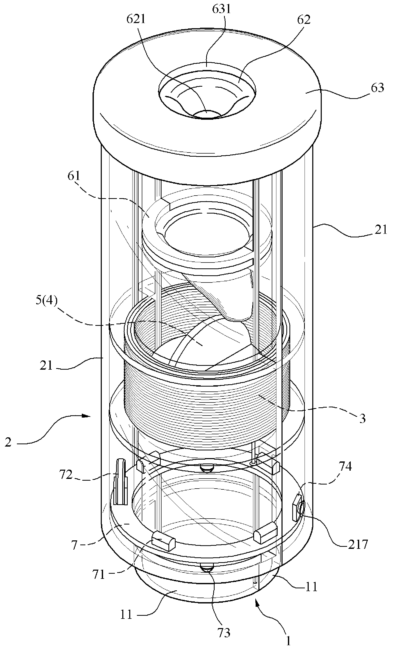
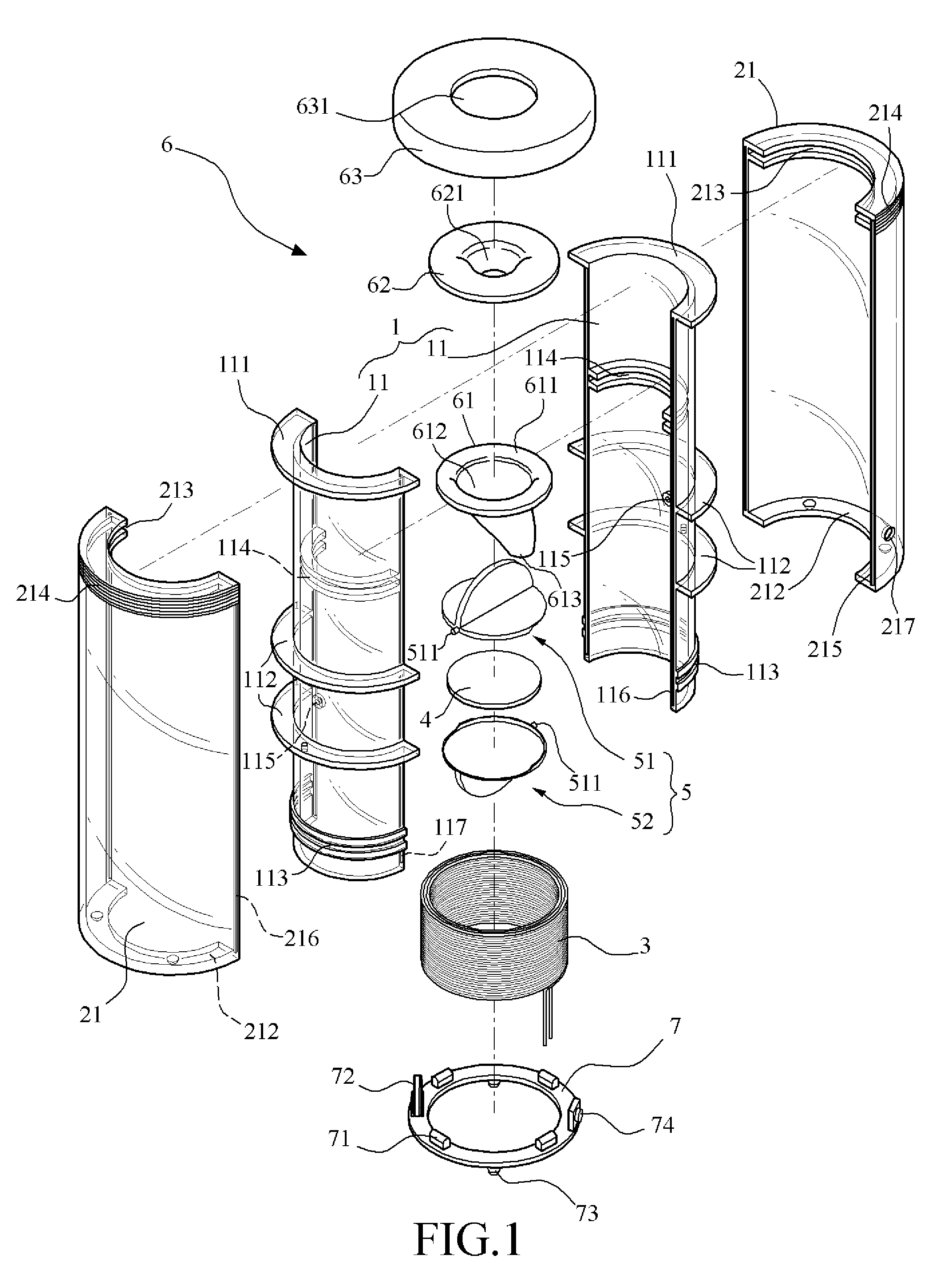
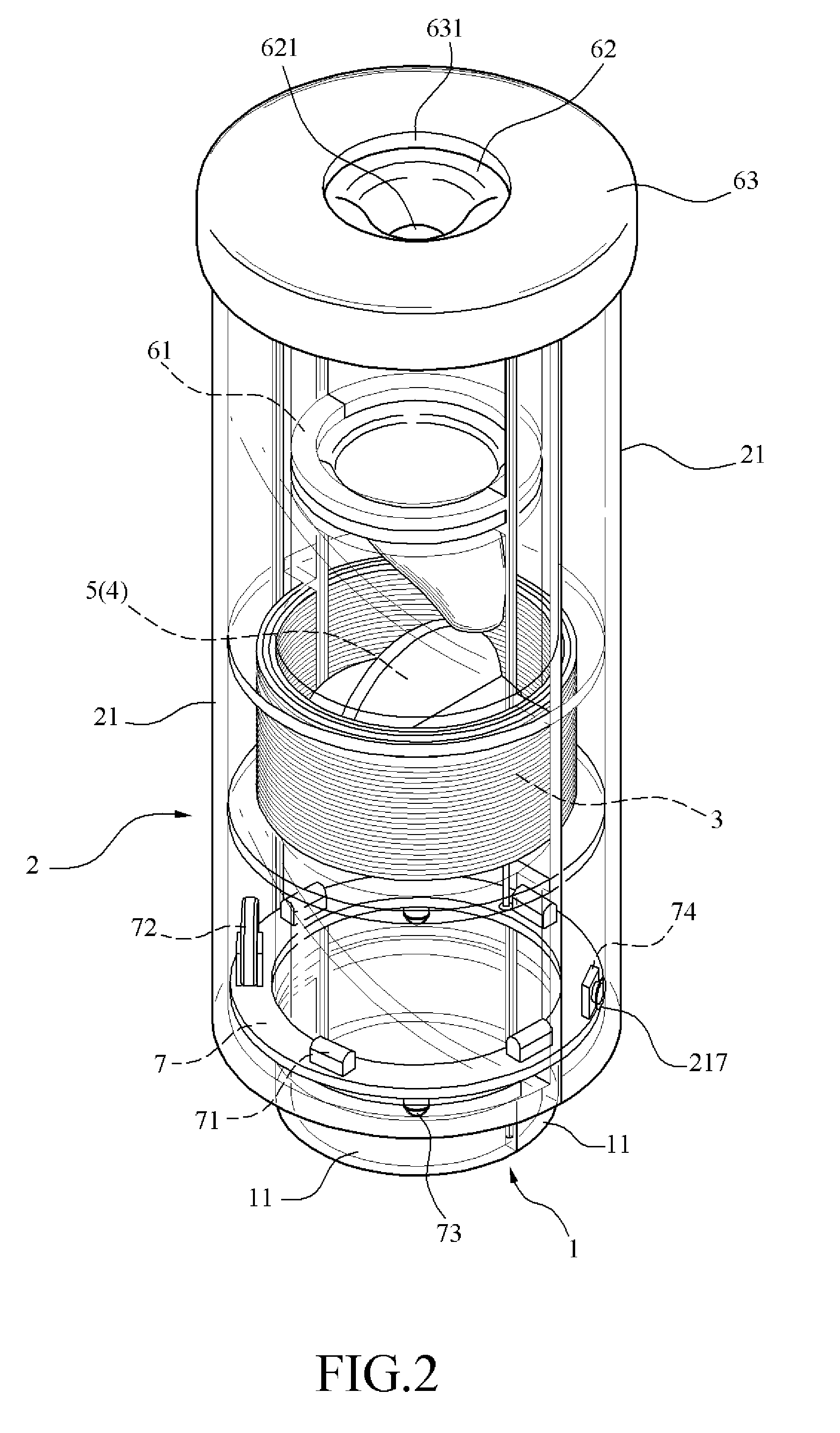
[0019]Referring to FIGS. 1 to 6, a mini-turbine in accordance with a first preferred embodiment of the invention is shown. The mini-turbine comprises the following components as discussed in detail below.

[0020]A hollow inner cylinder 1 comprises two half sections 11. The inner cylinder 1 has an annular flange 111 around a top opening (not numbered) as inlet. Either half section 11 has a lateral bossed hole 115 in an intermediate portion, an arc shaped groove 114 on an inner surface between the top opening and the hole 115, a lower arc shaped trough 113 on an outer surface, and two arc shaped flanges 112 on an outer surface in which one flange 112 is above the hole 115 and the other flange 112 is below the hole 115. Moreover, one half section 11 has two mating members 117 on both longitudinal edges and the other half section 11 has two corresponding mating members 116 on both longitudinal edges, the corresponding mating members 116 being adapted to lockingly engage with the mating me...


PUM


Abstract

A mini-turbine includes a hollow inner cylinder adapted to connect to a fluid source; a rotor disposed in and rotatably connected to the inner cylinder, the rotor comprising blades and an enclosed permanent magnet for producing a magnetic field; a winding mounted around the inner cylinder and being about flush with the rotor; a hollow outer cylinder mounted around the inner cylinder in a spaced fashion; and a nozzle disposed at a top opening of the inner cylinder and above the rotor. In one embodiment, pressurized water from a faucet may impinge upon the blades to rotate the rotor after passing the nozzle so that the rotor may cut lines of magnetic flux in the magnetic field to generate an induced AC voltage in the winding.

Description

BACKGROUND OF THE INVENTION[0001]1. Field of Invention[0002]The invention relates to electricity generation equipment and more particularly to a mini-turbine driven by fluid power (e.g., pressurized liquid or compressed gas) to generate electricity for illumination or low power applications.[0003]2. Description of Related Art[0004]Conventionally, alternators are large, heavy devices and designed for specific applications. However, so far as the inventor is aware, there are no mini-alternators to generate electricity for illumination or low power applications disclosed in any documents or commercially available. Hence, a need has arisen for a mini-turbine.SUMMARY OF THE INVENTION[0005]It is therefore one object of the invention to provide a mini-turbine driven by fluid power (e.g., pressurized liquid or compressed gas) to generate electricity for illumination or low power applications.[0006]To achieve the above and other objects, the invention provides a mini-turbine comprising a hol...

Claims


Application Information

Patent Timeline
Patent Type & Authority Applications(United States)
IPC IPC(8): H02K7/18
CPCH02K21/145H02K7/1823F05B2220/20F03B13/00
Inventor TU, SENG-DATU, UAN-IU
Owner TU SENG
Learn More