
Autonomous experimental design optimization

a design optimization and experimental technology, applied in the field of aerodynamic and hydrodynamic design optimization, can solve the problems of increasing the difficulty of solving problems, increasing the cost of simulation, and needing a relatively large number of evaluations, so as to speed up the optimization process

Inactive Publication Date: 2010-12-02
HONDA RES INST EUROPE
View PDF7 Cites 14 Cited by
  • Summary
  • Abstract
  • Description
  • Claims
  • Application Information

AI Technical Summary

Benefits of technology

This patent is about a method for optimizing the design of aerodynamic and hydrodynamic surfaces, such as aircraft, ships, and vehicles. The invention involves using a combination of computational fluid dynamics (CFD) and artificial neural networks (ANNs) to predict the effects of various design changes. The method is based on the idea of iterative optimization, which involves iteratively adjusting design parameters to find the best solution. The use of ANNs helps to approximate the results of CFD computations and allows for faster and more efficient design optimization. The patent also describes the use of experimental design optimization techniques using evolutionary algorithms, which involve using trial and error to find the best solution. Overall, the invention provides a more efficient and robust method for optimizing the design of aerodynamic and hydrodynamic surfaces.

Problems solved by technology

However, CFD simulations are computationally very expensive.
What makes the problem more difficult is that EAs need a relatively large number of evaluations in order to achieve a near optimal aerodynamic design.
An important issue that is closely related to ANNs is learning.
Consequently, this approach has been widely used for many design problems including wing design, nozzle design, supersonic wing-body design, and more complex aircraft configurations.
The quality landscape for an aerodynamic design problem, however, is usually multimodal.
In this sense, GMs are neither efficient nor robust for design optimization.
This process can be computationally expensive and in general it is not very robust against noise.
However, Otto et al. do not disclose the use of EAs for said optimization process.

Method used


Image

  • Autonomous experimental design optimization
  • Autonomous experimental design optimization
  • Autonomous experimental design optimization

Examples


Embodiment Construction

[0028]In the following description, embodiments of the present invention as depicted in FIGS. 1 to 6 shall be explained in detail. As an overview, the following is a brief description of the elements in the diagrams, charts, and illustrations of the figures.

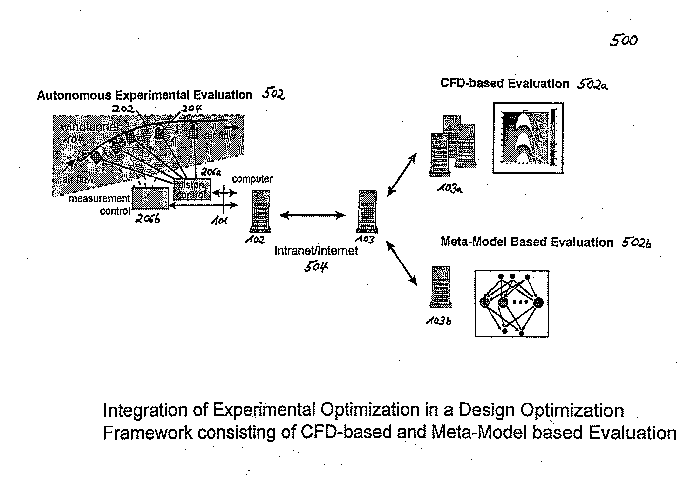
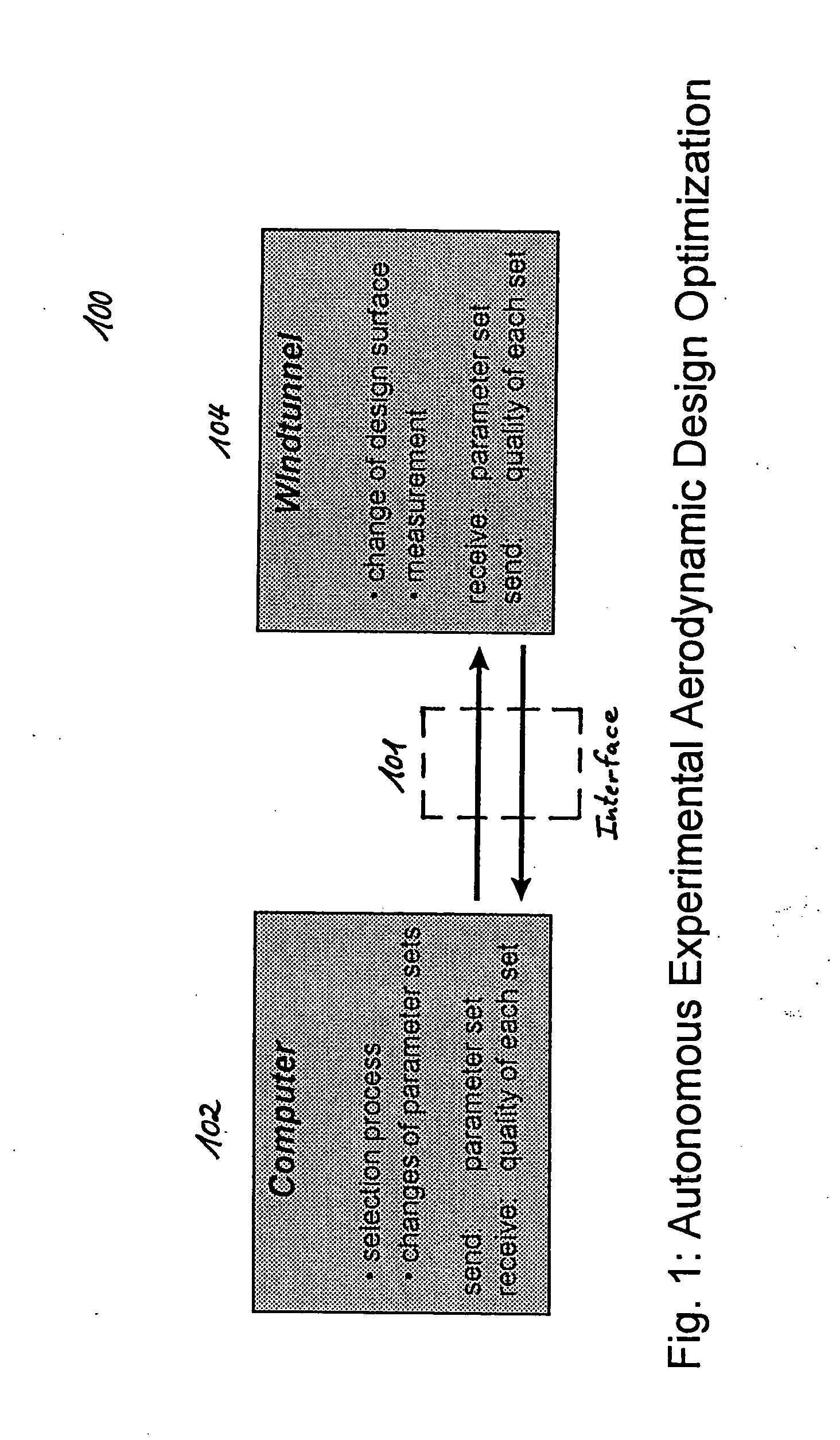
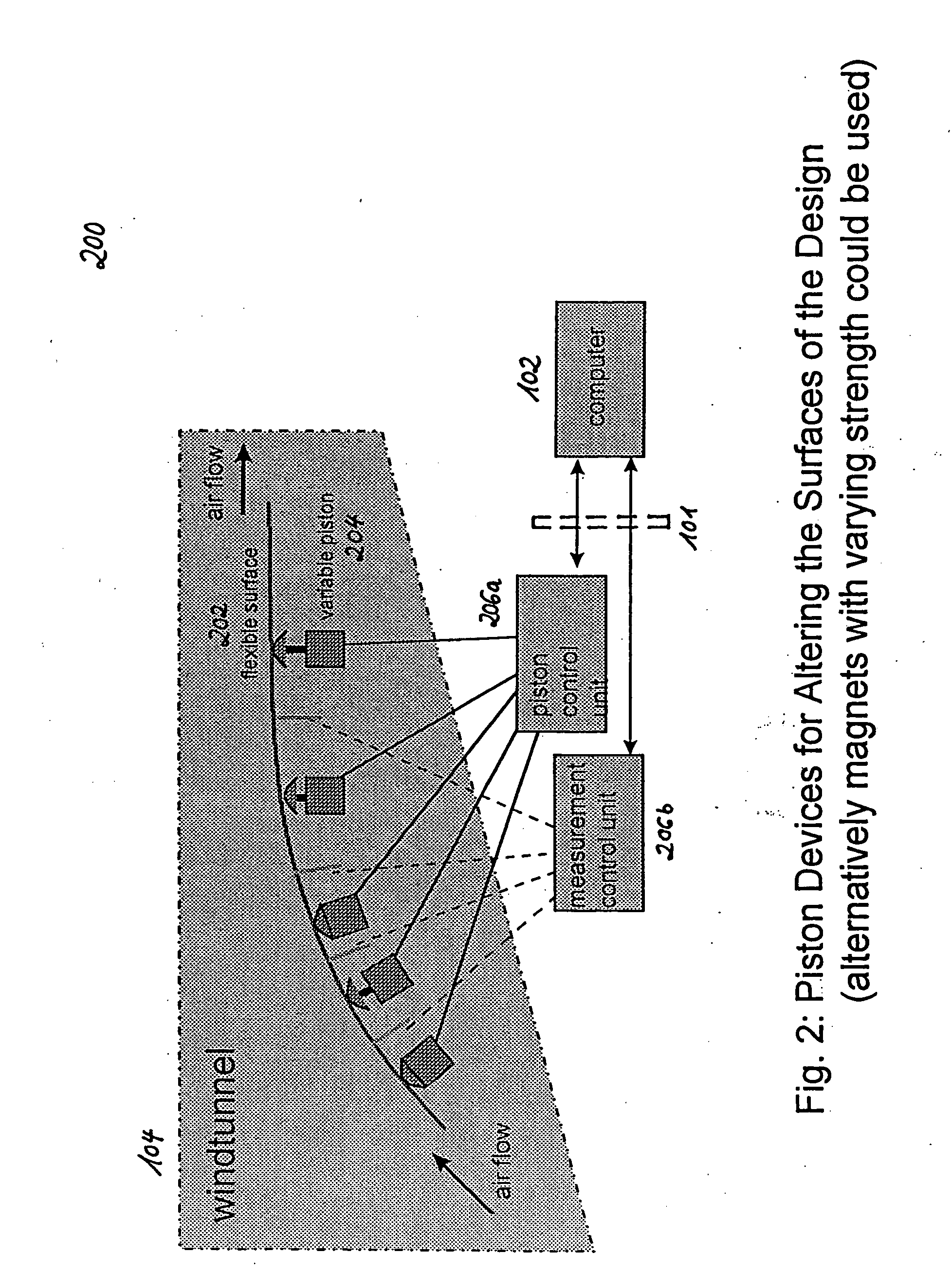
[0029]System 100 embodies the principle of the autonomous experimental aerodynamic design optimization technique according to the one embodiment of the present invention. Interface 101 is the interface between the computing device 102 and the wind tunnel 104 in one embodiment of the present invention. Computing device 102 is a client PC needed for the selection process according to the evolution strategy and the calculation of optimized parameter sets according one optimization algorithm embodiment of the present invention. Server 103 is a first application server connected to the client PC 102 via the Internet 504 or any corporate network (Intranet), which hosts the optimization algorithm according to one embodiment of the prese...


PUM


Abstract

Iterative (nondeterministic) optimization of aerodynamic and hydrodynamic surface structures can be accomplished with a computer software program and a system using a combination of a variable encoding length optimization algorithm based on an evolution strategy and an experimental hardware set-up that allows to automatically change the surface properties of the applied material, starting with the overall shape and proceeding via more detailed modifications in local surface areas. The optimization of surface structures may be done with a computing device for calculating optimized parameters of at least one (virtual) surface structure, an experimental hardware set-up for measuring dynamic properties of a specific surface structure, and an interface for feeding calculated parameters from the computing device to the experimental set-up and for feeding measured results back to the computing device as quality values for the next cycle of the optimizing step.

Description

RELATED FOREIGN APPLICATIONS[0001]This application is related and claims priority to European Patent Application No. 02 013 826.9 filed on Jun. 21, 2002 by Bernhard Sendhoff, Edgar Korner, and Andreas Richter, titled “Autonomous Experimental Design Optimization”.FIELD OF THE INVENTION[0002]The underlying invention generally relates to the optimization of aerodynamic and hydrodynamic designs, in particular to methods for an iterative (non-deterministic) optimization of hydrodynamic and aerodynamic surfaces, e.g., aircrafts, ships and vehicles, a computer software program for implementing such a method as well as to systems for optimizing said surfaces.BACKGROUND OF THE INVENTION[0003]Some aspects of the invention involve the advantageous use of technologies known in the art. In the following description some of these basic technologies will be introduced, for example, CFD, Gradient based methods, Evolutionary Algorithms (EA), and Artificial 25 Neuronal Networks (ANN).[0004]Computatio...

Claims


Application Information

Patent Timeline
Patent Type & Authority Applications(United States)
IPC IPC(8): G06G7/48G06F17/50
CPCG06F17/5095Y02T90/50G06F2217/16G06F2217/08G06F2111/06G06F2111/10G06F30/15Y02T90/00
Inventor SENDHOFF, BERNHARD A.KORNER, EDGARRICHTER, ANDREAS
Owner HONDA RES INST EUROPE
Learn More