Flash heat ammonia generator

a technology of ammonia generator and ammonia gas, which is applied in the direction of machines/engines, mechanical equipment, chemical/physical/physicochemical processes, etc., can solve the problems of reducing the efficiency of the urea injection system, and adding both weight and cost to the vehicl

Inactive Publication Date: 2010-12-02
DELPHI TECH HLDG S A R L
View PDF7 Cites 11 Cited by
  • Summary
  • Abstract
  • Description
  • Claims
  • Application Information

AI Technical Summary

Problems solved by technology

During certain operating conditions, such as extreme cold temperatures, the ammonia or urea solution may become frozen, particularly below the freezing temperature of urea solution, e.g., −12° C., thereby losing the ability to inject the solution into the exhaust gas stream.
The use of cool urea solution leads to the development of crystallized urea on the urea injector, exhaust components or exhaust treatment device, also reducing the efficiency of the urea injection system.
This adds both weight and cost to the vehicle.

Method used


Image

  • Flash heat ammonia generator
  • Flash heat ammonia generator
  • Flash heat ammonia generator

Examples


Embodiment Construction

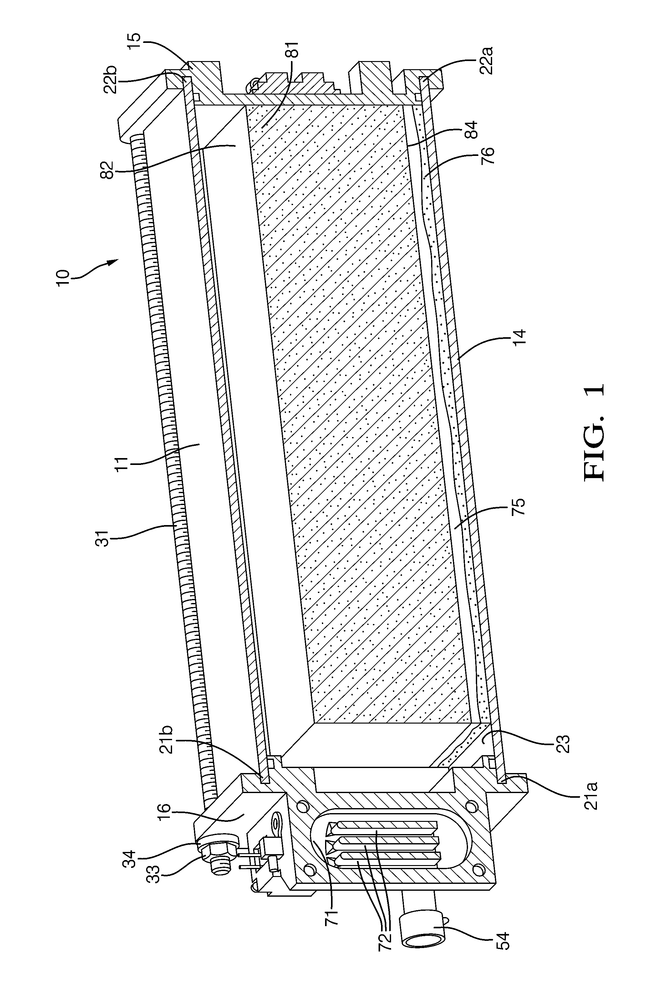
[0022]Referring now to the Figures and the Appendix (the entirety of which is incorporated by reference herein), where the invention will be described with reference to specific embodiments, without limiting same, a cross section through an ammonia generator pressure vessel reactor 10 is shown in FIGS. 1, 2 and 3. Additional details are shown in the Appendix. The ammonia generator is comprised of side walls 11, 12, 13 and 14, with end walls 15 and 16 to form a rectangular configuration.

[0023]As shown in FIG. 1, side walls 11, 12, 13, and 14 fit into notches 21 and 22 located within end walls 15 and 16 to form a cavity 23 within ammonia generator 10. End walls 11, 12, 13 and 14 are retained within notches 21 by threaded screw stock 31 that spans the length of ammonia generator 10 and is retained in opposing end walls 15 and 16 by extending through holes 32 and retained in compression by nuts 33 and washers 34. In this way, a pressure vessel 10 having a rectangular cross-section is cr...


PUM

PropertyMeasurementUnit
temperaturesaaaaaaaaaa
temperatureaaaaaaaaaa
freezing temperatureaaaaaaaaaa

Abstract

An ammonia producing device for an exhaust system of an engine is provided. It includes a pressure vessel having a cavity for storage of pressurized gases. The pressure vessel includes insulation located at least partially about the cavity for limiting heat transfer from within the cavity. A flash heater is disposed within the cavity and adjacent a solid ammonia gas producing material. An outlet port extends from the pressure vessel and has a valve located therein for providing egress of pressurized gases from within the pressure vessel.

Description

CROSS REFERENCE TO RELATED APPLICATIONS[0001]This application claims priority to U.S. Provisional Application No. 61 / 182,968, filed Jun. 1, 2009, the contents of which are incorporated by reference herein.BACKGROUND OF THE INVENTION[0002]Exhaust emission control has been and will continue to be of interest as effects of emissions from stationary and transient emission generating devices are continually being understood. This, along with government mandates, have caused manufacturers of emission generating devices, particularly internal combustion engines, to develop methods and devices for controlling the content of emissions emanating from such devices. In one particular sector, due to the advantages of diesel burning engines over gasoline burning engines, advancements of emission control for diesel engines are continuingly being sought. These advancements include emission control devices configured for removing particulate matter from an exhaust gas stream and Selective Catalyst R...

Claims


Application Information

Patent Timeline
Patent Type & Authority Applications(United States)
IPC IPC(8): F01N3/10C01C1/00C01C1/02B01J19/00
CPCC01C1/006C01C1/026C01C1/08F01N3/2066F01N2610/10F01N2610/02F01N2610/06F01N2610/1406F01N2240/25
Inventor FULKS, GARY C.RAHMOELLER, KENNETH M.
Owner DELPHI TECH HLDG S A R L
Why Eureka
Try Eureka