Fuel cell system
a fuel cell and system technology, applied in the field of fuel cell systems, can solve the problems of shortened life, and inability to generate the amount of hydrogen required for electric power generation of the fuel cell, and achieve the effect of preventing the deterioration of the reforming catalys
- Summary
- Abstract
- Description
- Claims
- Application Information
AI Technical Summary
Benefits of technology
Problems solved by technology
Method used
Image
Examples
embodiment 1
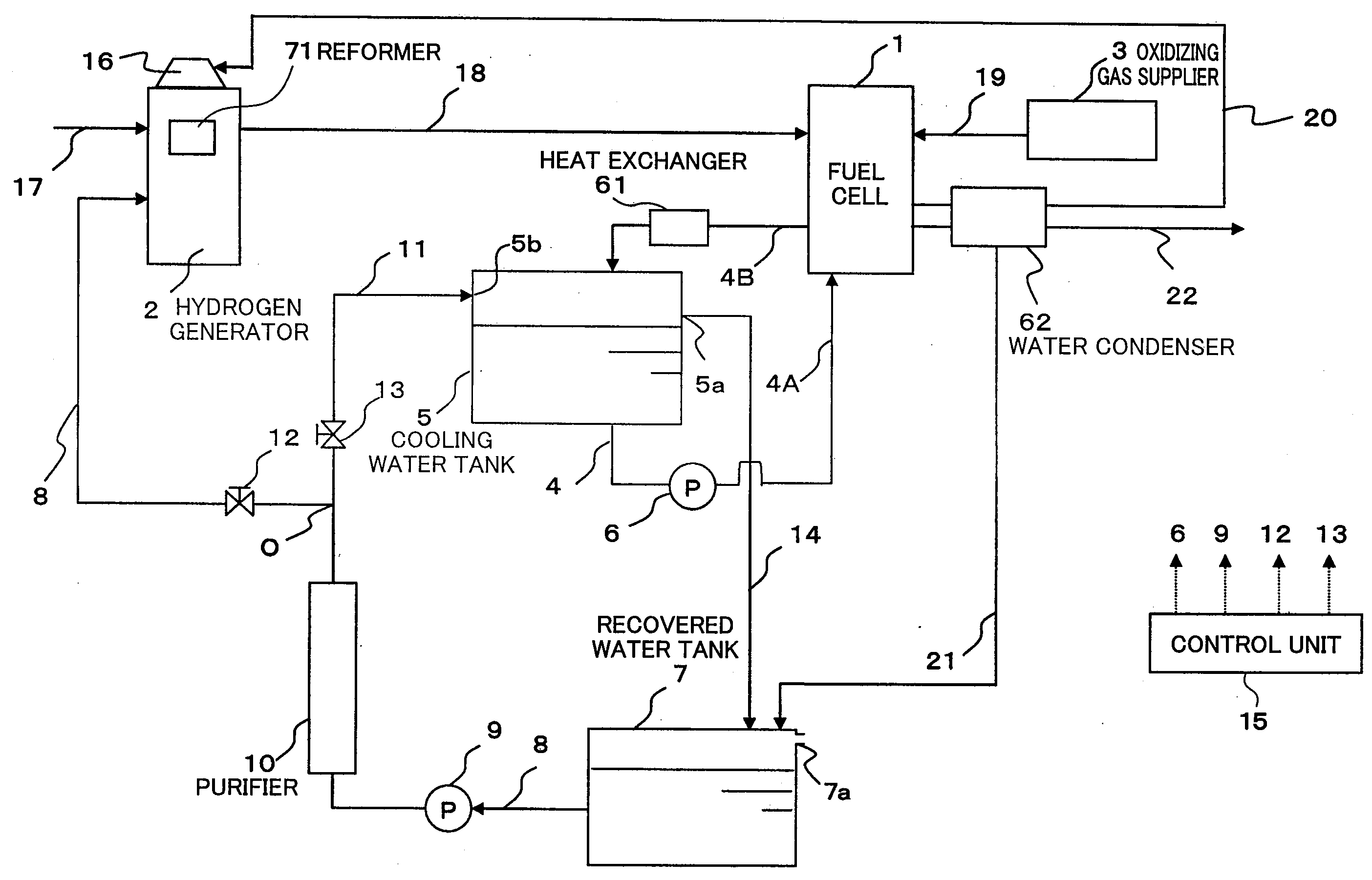
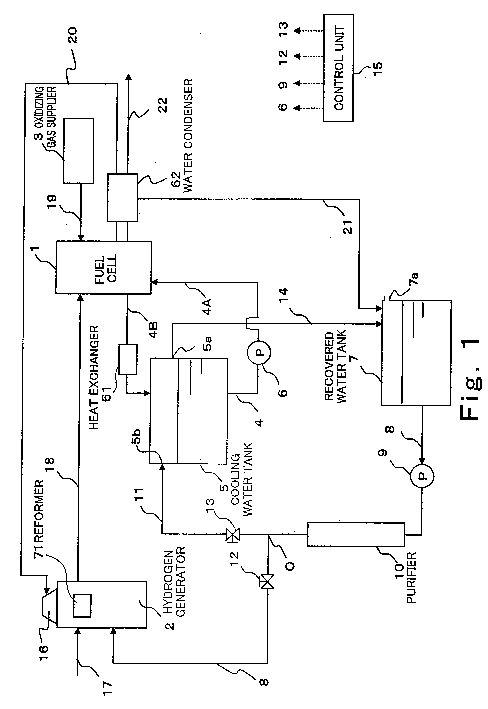
[0109]FIG. 1 is a configuration diagram of a fuel cell system according to Embodiment 1 of the present invention.
[0110]As shown in FIG. 1, the fuel cell system of Embodiment 1 includes: a fuel cell 1 configured to generate electric power using a hydrogen-containing fuel gas and an oxidizing gas; a hydrogen generator 2 incorporating a reformer 71 configured to carry out steam reforming of a raw material, such as a city gas, to generate a hydrogen-rich fuel gas; a material supplying passage 17 through which a material gas, such as a city gas, is supplied to the reformer; a fuel gas supplying passage 18 through which the hydrogen-rich fuel gas is supplied from the hydrogen generator 2 to the fuel cell 1; and an oxidizing gas supplier 3 which supplies the oxidizing gas through an oxidizing gas supplying passage 19 to the fuel cell 1.
[0111]In addition to the reformer 71, the hydrogen generator 2 further incorporates: a shift converter (not shown) configured to reduce, by a shift reaction...
embodiment 2
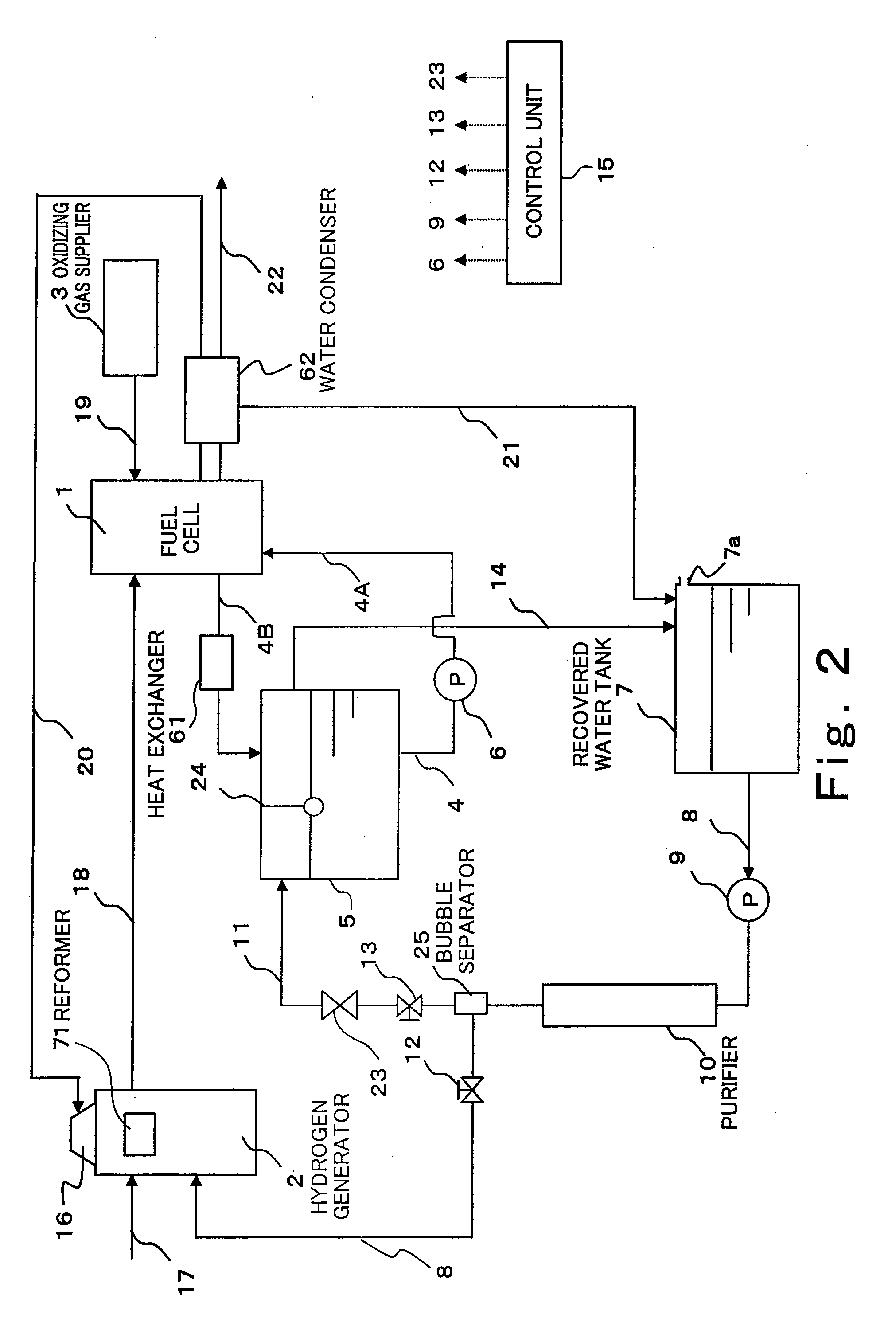
[0144]FIG. 2 is a configuration diagram showing the fuel cell system according to Embodiment 2 of the present invention. The fuel cell system of Embodiment 2 is the same in basic configuration as that of Embodiment 1, but is different from that of Embodiment 1 regarding a component disposed on the second water passage 11 and the configuration of the cooling water tank 5. Therefore, these differences therebetween will be mainly explained, and explanations of the configurations and operations common to those of Embodiment 1 are omitted.
[0145]As shown in FIG. 2, the fuel cell system according to Embodiment 2 of the present invention includes: a water supplying valve 23 disposed on the second water passage 11 to block the water supply to the cooling water tank 5; a water level detector 24 configured to detect the water level of the cooling water tank 5; and a bubble separator 25 disposed on a connection portion of the first water passage 8 and the second water passage 11 to separate the...
embodiment 3
[0160]FIG. 4 is a block diagram showing the configuration of the fuel cell system according to Embodiment 4 of the present invention. As shown in FIG. 4, the fuel cell system of Embodiment 3 is the same in basic configuration as that of Embodiment 1, but the following points are mainly different therebetween. Hereinafter, the different configurations and operations will be mainly explained, and explanations of the configurations and operations common to those of Embodiment 1 are omitted.
[0161]Instead of the orifice A12 and the orifice B13 in Embodiment 1, the fuel cell system of Embodiment 3 includes a reforming water valve 75 and a cooling water valve 76. Each of the reforming water valve 75 and the cooling water valve 76 is constituted by an on-off valve, and operations thereof are controlled by the control unit 15. In a case where the reforming water valve 75 opens and the cooling water valve 76 closes, the water is supplied from the recovered water tank 7 to the reformer 71 of t...
PUM
 Abstract
Description
Claims
Application Information
 - R&D
- Intellectual Property
- Life Sciences
- Materials
- Tech Scout
- Unparalleled Data Quality
- Higher Quality Content
- 60% Fewer Hallucinations
Browse by: Latest US Patents, China's latest patents, Technical Efficacy Thesaurus, Application Domain, Technology Topic, Popular Technical Reports.
© 2025 PatSnap. All rights reserved.Legal|Privacy policy|Modern Slavery Act Transparency Statement|Sitemap|About US| Contact US: help@patsnap.com


