Wireless communication system, base station, terminal and wireless communication method

Inactive Publication Date: 2010-11-25
KYOCERA CORP
View PDF5 Cites 1 Cited by
  • Summary
  • Abstract
  • Description
  • Claims
  • Application Information

AI Technical Summary

Benefits of technology

[0006]The present invention was conceived to solve the above-described problems and has an object of, when using the multicarrier communication, reducing the peak factor by randomizing data between the sub-channels without both increased cost and low communication speed.
[0017]By using the present invention, it is not necessary to include storing portions for storing the scramble data in accordance with a number of sub-channels, and it is possible to avoid an increase in cost. In addition, regarding a base station, when the base station is started, and regarding a terminal, when the terminal establishes a communication connection with the base station which is at the other end of a communication, the scramble data is stored in the storing portion, and in a communication conducted afterward, a randomizing (scramble) operation is conducted on data between sub-channels by using the scramble data stored in the storing portion. Therefore, a problem is not caused in which the communication speed is deteriorated by using such a method of generating the scramble data every time the data is transmitted. Hence, in the present invention, when using the multicarrier communication, it is possible to reduce the peak factor by randomizing data between the sub-channels without both increased cost and low communication speed.

Problems solved by technology

However, the same scrambling operation is conducted on each sub-channel, and a problem is caused in which a peak factor is increased.
However, in accordance with such a method, it is necessary to provide memory for storing the scramble data in accordance with a number of sub-channels, and a problem of increased cost is caused.
However, in accordance with such a method, a problem of low communication speed is caused.

Method used


Image

  • Wireless communication system, base station, terminal and wireless communication method
  • Wireless communication system, base station, terminal and wireless communication method
  • Wireless communication system, base station, terminal and wireless communication method

Examples


Embodiment Construction

[0050]Hereinafter, preferable embodiments of the present invention are explained in reference to the drawings. However, the present invention is not limited by the embodiments explained below, and for example, it is possible to appropriately combine constitutional elements of the embodiments.

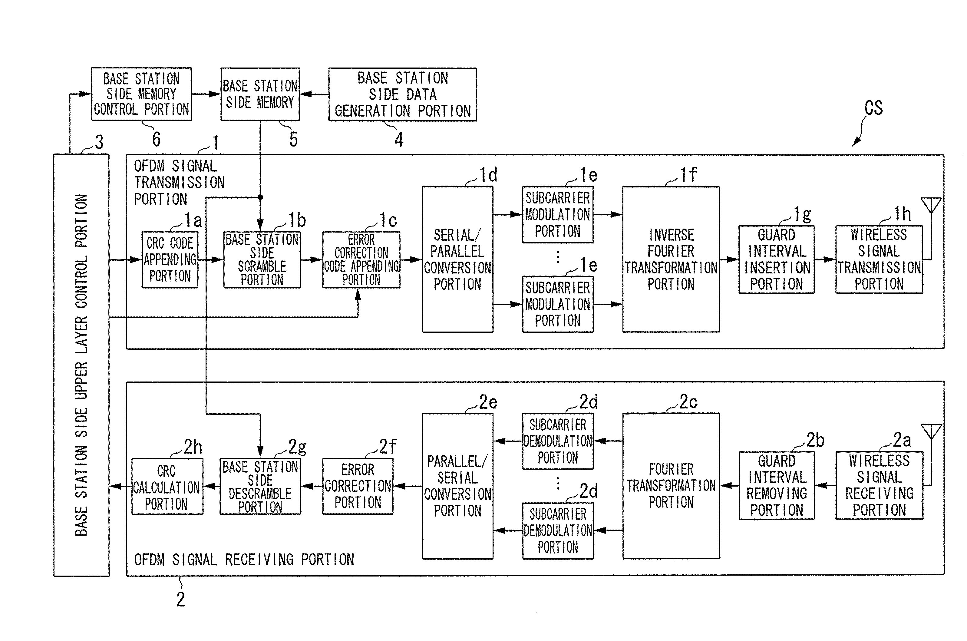
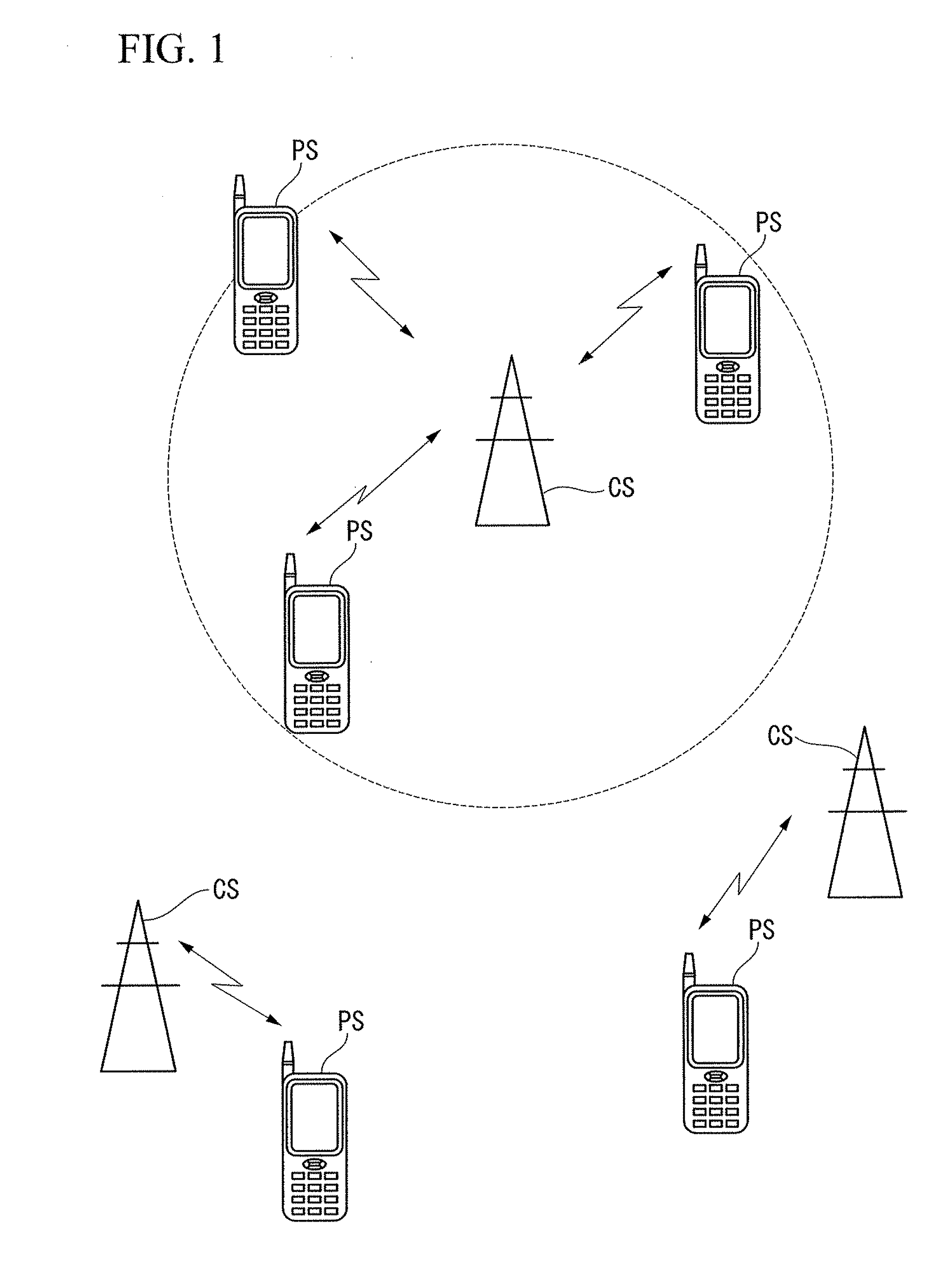
[0051]First, one embodiment of the present invention is explained in details in reference to an example of a wireless communication system to which OFDM method is applied for a multicarrier communication. As shown in FIG. 1, a wireless communication system of this embodiment is constituted from base stations CS, terminals PS and a network which is not shown in the drawings. The base stations CS and the terminals PS conduct a communication by using a multi-access technique which is, for example, a time division multiple access (TDMA) method, a time division duplex (TDD) method and in addition, an orthogonal frequency division multiplex access (OFDMA) method. The base stations CS are multiple, are...


PUM


Abstract

A base station of a wireless communication system includes: a base station side data generation portion generating a number of sets of scramble data which are different from each other while the number of sets of the scramble data is the same as or more than the number obtained by multiplying the number of the sub-channels used in said overall wireless communication system by the number of the subcarriers; a base station side storage portion which stores the scramble data; a base station side upper layer control portion which outputs both transmission data for a terminal at other end of a communication and information of sub-channels; a base station side lower layer control portion which, based on the information of the sub-channels, controls the base station side storage portion to output scramble data corresponding to the sub-channels; a base station side scramble portion which conducts a multiplication operation between the transmission data output from the base station side upper layer control portion and the scramble data output from the base station side storage portion based on a control by the base station side lower layer control portion.

Description

TECHNICAL FIELD[0001]The present application relates a wireless communication system, a base station, a terminal and a wireless communication method.[0002]Priority is claimed on Japanese Patent Applications No. 2007-281690, filed Oct. 30, 2007, the content of which is incorporated herein by reference.BACKGROUND ART[0003]In recent years, multicarrier communication systems, for example, OFDM (Orthogonal Frequency Division Multiplexing) and OFDMA (Orthogonal Frequency Division Multiple Access) are remarkably recognized as next generation broadband mobile communication systems. For example, OFDM is a technique which realizes multi-access by sharing subcarriers mutually in orthogonal relationship between multiple terminals, assigning arbitrarily selected multiple subcarriers as sub-channels and adaptively assigning a sub-channel to each terminal at an arbitral time (in a system to which TDMA is applied, such a communication time corresponds to, for example, a slot). In Patent Document 1 ...

Claims


Application Information

Patent Timeline
IPC IPC(8): H04K1/10H04K1/00
CPCH04K1/00H04L1/0041H04L27/2621H04L25/03866H04L27/2613H04L1/0061H04L27/2628
Inventor SAHARA, TORU
Owner KYOCERA CORP
Why Eureka
Try Eureka