
Method and device for regulating a polyphase rotating electrical machine operating as a generator, and polyphase rotating electrical machine using them

a technology of polyphase rotating electrical machines and generators, applied in the direction of electric variable regulation, electric generator control, instruments, etc., can solve the problems of increasing the temperature of the chip, and thus the frequency cannot be increased, and achieve the effect of improving the regulation bandwidth

Active Publication Date: 2010-11-25
VALEO EQUIP ELECTRIC MOTEUR
View PDF8 Cites 17 Cited by
  • Summary
  • Abstract
  • Description
  • Claims
  • Application Information

AI Technical Summary

Benefits of technology

The present invention is about improving the regulation bandwidth of a polyphase rotating electrical machine operating as a generator without modifying the switching frequency of the excitation current. This is achieved by a method of regulation that involves determining the duty cycle of the excitation current twice during the cycle of the machine, using a microcontroller or similar device. The method involves calculating the first and second switching times as a function of the DC voltage generated by the machine. The invention also includes a device for regulating the machine, comprising a microcontroller, analog-digital converter, PWM generator, amplifier, and at least one transistor controlled by the PWM pulses. The invention provides improved regulation bandwidth without modifying the switching frequency of the excitation current.

Problems solved by technology

This dissipated power leads to a rise in the temperature of the chip, which is itself limited by the maximum junction temperature permitted by the technology utilised.
This frequency thus cannot be increased without giving rise to new temperature constraints on the switching component.

Method used


Image

  • Method and device for regulating a polyphase rotating electrical machine operating as a generator, and polyphase rotating electrical machine using them
  • Method and device for regulating a polyphase rotating electrical machine operating as a generator, and polyphase rotating electrical machine using them
  • Method and device for regulating a polyphase rotating electrical machine operating as a generator, and polyphase rotating electrical machine using them

Examples


Embodiment Construction

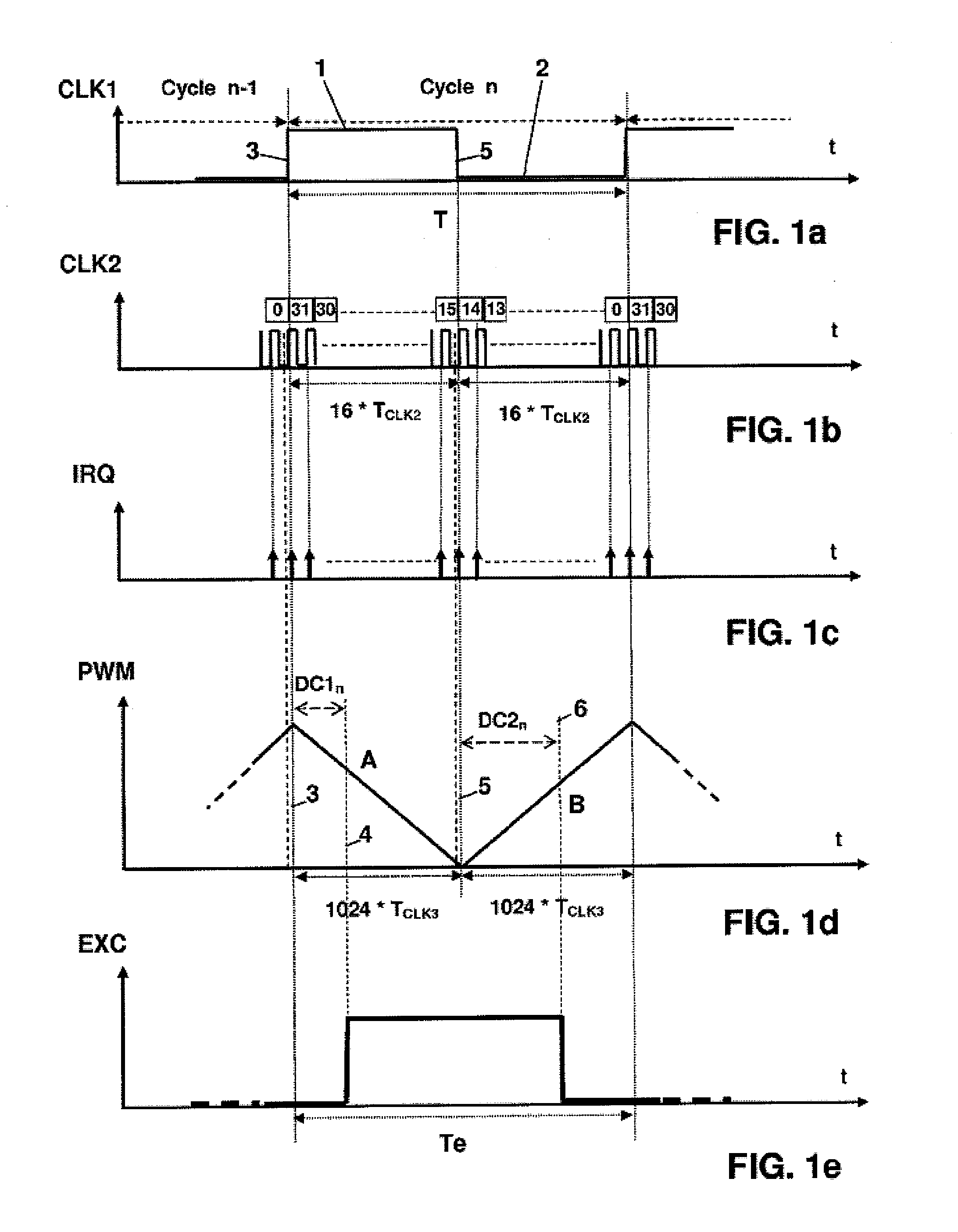
[0051]The method according to the invention thus essentially consists of increasing the apparent frequency of the regulation loop without modifying the chopping frequency of the excitation transistor in order not to increase the switching losses in the transistor, and hence the junction temperature of the component.

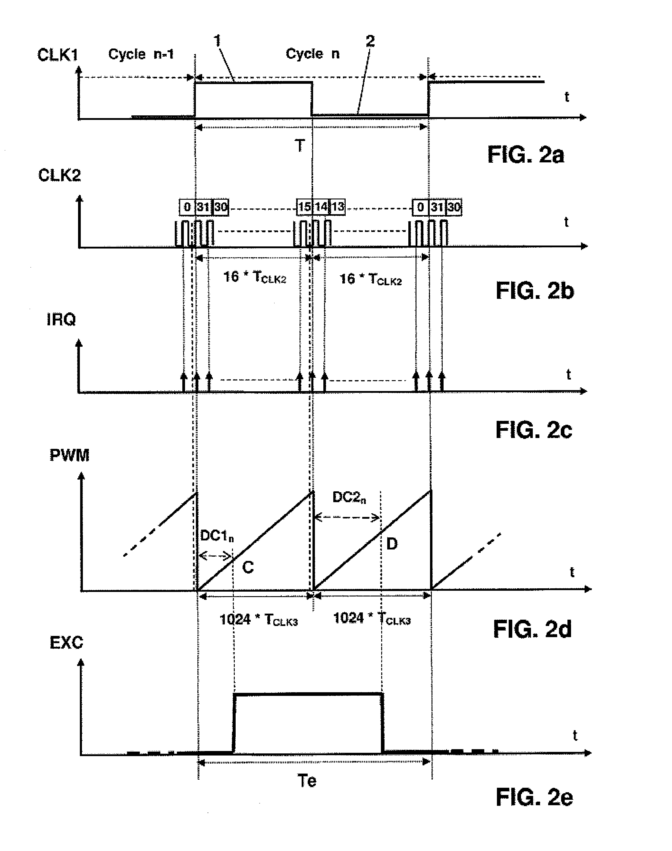
[0052]FIG. 1a represents the first clock pulses CLK1 controlling the cycles of the regulation loop, the first period of which, T, is equal to the excitation period Te of the PWM control pulses EXC of the excitation current represented in FIG. 1e.

[0053]Fundamentally, according to the method of the invention, the first period T of the first clock pulses CLK1 is not reduced, hence nor is the excitation period Te, but the duty cycle is refreshed twice during a chopping period Te of the transistor.

[0054]In the first half of cycle 1, the regulator will decide on the basis of a first measurement of the quantity to be controlled at the instant the power transistor goes into the ...


PUM


Abstract

The regulating method is employed in a polyphase rotating electrical machine operating as a generator and having an excitation coil (10). The method is of the type in which a DC voltage (B+) is slaved to a predetermined setpoint, the voltage being produced by rectifying an AC voltage generated by the machine by controlling the duty cycle of a periodic excitation current (+EXC,−EXC) by means of a microcontroller (11), or the like, as a function of sampled values of the DC voltage (B+). The duty cycle is determined by the microcontroller (11) twice during an excitation current cycle (+EXC, −EXC).

Description

TECHNICAL DOMAIN OF THE INVENTION[0001]The present invention concerns a method and a device for regulating a polyphase rotating electrical machine, especially of the alternator or alternator-starter type, comprising an excitation coil and operating as a generator. The invention also concerns a rotating electrical machine utilising this method and this device.TECHNOLOGICAL BACKGROUND TO THE INVENTION[0002]With a view to reducing energy consumption, it is now becoming common to stop the thermal engine of a vehicle when it comes to a halt, and to restart the engine motor to move off again, in a way which is automatic and totally transparent for the driver.[0003]This is possible due to the development of alternator-starters, which have been rendered highly efficient by the use of electronic power systems controlled by circuits which rely on digital techniques, mainly based on the use of microprocessors or microcontrollers.[0004]One example of such techniques is provided in the document ...

Claims


Application Information

Patent Timeline
Patent Type & Authority Applications(United States)
IPC IPC(8): H02P9/30
CPCH02P23/0077H02P9/305
Inventor MATT, JEAN-CLAUDELOUISE, CHRISTOPHE
Owner VALEO EQUIP ELECTRIC MOTEUR
Learn More