
Spectral shift control for dimmable AC led lighting

A light engine, current path technology, applied in the field of lighting systems, can solve problems such as distorted current waveforms

Active Publication Date: 2012-07-25
SIGNIFY NORTH AMERICA CORP
View PDF7 Cites 8 Cited by
  • Summary
  • Abstract
  • Description
  • Claims
  • Application Information

AI Technical Summary

Problems solved by technology

Non-linear loads such as rectifier loads can cause distorted current waveforms

Method used


Image

  • Spectral shift control for dimmable AC led lighting
  • Spectral shift control for dimmable AC led lighting
  • Spectral shift control for dimmable AC led lighting

Examples


Embodiment Construction

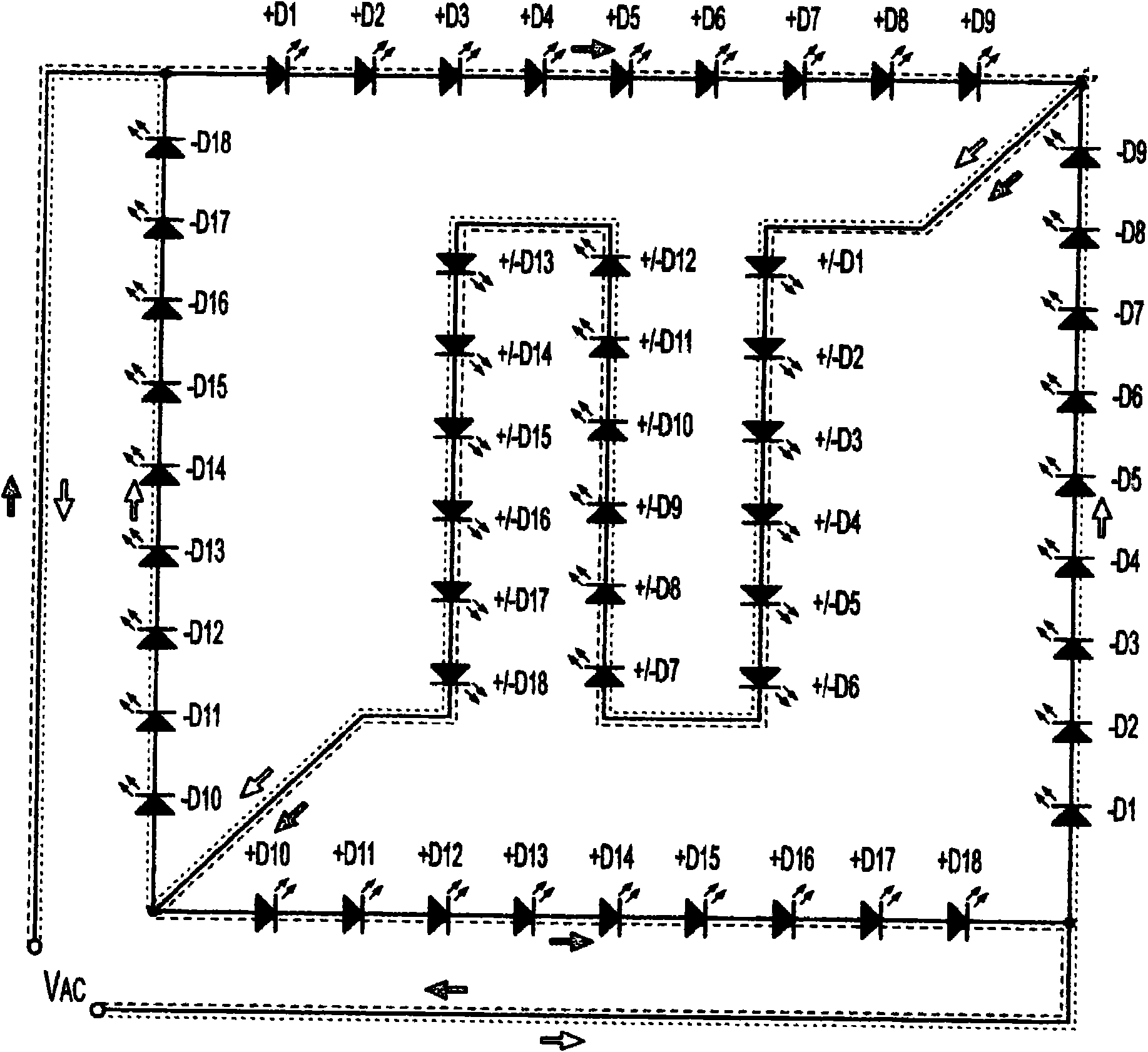
[0043] To facilitate understanding, the overall organization of this document is as follows. First of all, in order to facilitate the introduction of the discussion about each embodiment, refer to Figure 1-5 A lighting system with a full-wave rectifier topology using LEDs is presented. Second, through this introduction, reference is introduced to Figure 6-9A description of some exemplary embodiments of a full wave rectifier lighting system employing selective shunting to improve power factor capability. Third, refer to Figure 10-13 Selective shunting applied in an exemplary LED string configured as half-wave rectification is described. Fourth, refer to Figure 14-19 , the discussion turns to an exemplary embodiment illustrating selective shunting applied in LED strings using conventional (eg, non-LED) rectifiers. Fifth, refer to Figure 20 , this document describes exemplary apparatus and methods for calibrating or testing power factor improvement in an implementation...


PUM


Abstract

Apparatus and associated methods involve operation of an LED light engine in which a relative intensities of selected wavelengths shift as a function of electrical excitation. In an illustrative example, current may be selectively and automatically diverted substantially away from at least one of a number of LEDs arranged in a series circuit until the current or its associated periodic excitation voltage reaches a predetermined threshold level. The diversion current may be smoothly reduced in transition as the excitation current or voltage rises substantially above the predetermined threshold level. A color temperature of the light output may be substantially changed as a predetermined function of the excitation voltage. For example, some embodiments may substantially increase or decrease a color temperature output by a solid state light engine in response to dimming the AC voltage excitation (e.g., by phase-cutting or amplitude modulation).

Description

technical field [0001] Various embodiments generally relate to lighting systems that include light emitting diodes (LEDs). Background technique [0002] Power factor is very important for facilities that transmit electrical energy to consumers. Of two loads requiring the same level of real power, the load with the better power factor actually requires less current from the facility. A load with a power factor of 1.0 draws the least amount of current from the facility. Facilities can provide reduced power to customers with high power factor loads. [0003] A phase difference between voltage and current can result in poor power factor. Power factor is also degraded by the distortion and harmonic content of the current. In some cases, the distorted current waveform tends to increase the harmonic power content and reduce the power at the fundamental frequency. For a sinusoidal voltage waveform, only the fundamental frequency of the electrical energy can deliver real power t...

Claims


Application Information

Patent Timeline
Patent Type & Authority Applications(China)
IPC IPC(8): H05B41/00H05B44/00
CPCH05B33/0809H01L2924/3011H05B45/40H05B45/20H05B45/42H05B45/31H05B45/36H05B45/35H05B45/3725H01L2924/00H05B45/48H05B45/37
Inventor 兹登科·格拉卡
Owner SIGNIFY NORTH AMERICA CORP
Learn More