
State Estimator for Rejecting Noise and Tracking and Updating Bias in Inertial Sensors and Associated Methods

a state estimator and noise rejection technology, applied in surveying and navigation, instruments, navigation instruments, etc., can solve problems such as unbounded error growth, inability to use inertial measurement, and limited application of inertial sensors

Active Publication Date: 2010-11-18
UNIV OF UTAH RES FOUND
View PDF12 Cites 37 Cited by
  • Summary
  • Abstract
  • Description
  • Claims
  • Application Information

AI Technical Summary

Benefits of technology

[0007]The present invention provides methods and systems for tracking and updating bias in an inertial sensor. In one aspect, for example, a method for updating bias in a sensor during an extended period of periodic motion is provided. Such a method can include determining a maximum bias drift and a noise band for a sensor, determining a prior bias value of the sensor, and measuring a current bias value of the sensor. The method can further include calculating a bias difference between the prior bias value and the current bias value, and updating the prior bias value with the current bias value if the current bias value is within the noise band and the bias difference is less than or equal to the maximum bias drift. In one aspect, updating the bias value occurs in real time. In another aspect, updating the bias value occurs in real time during gait motions of a subject.

Problems solved by technology

Until recent years, applications better-suited to measurement using meters or millimeters generally did not utilize inertial measurement due to the prohibitive size, weight, and cost of the sensors.
Despite these advantages, applications of inertial sensors are still limited due to drawbacks that include bias drift, sensor accuracy, mounting, and calibration issues.
Since velocity, position, and orientation are all derived through integration, the results of which are sensitive to all of these potential sources of error, they lead to unbounded error growth if outside references are unavailable.

Method used


Image

  • State Estimator for Rejecting Noise and Tracking and Updating Bias in Inertial Sensors and Associated Methods
  • State Estimator for Rejecting Noise and Tracking and Updating Bias in Inertial Sensors and Associated Methods
  • State Estimator for Rejecting Noise and Tracking and Updating Bias in Inertial Sensors and Associated Methods

Examples


examples

Experimental Setup

[0046]Equipment

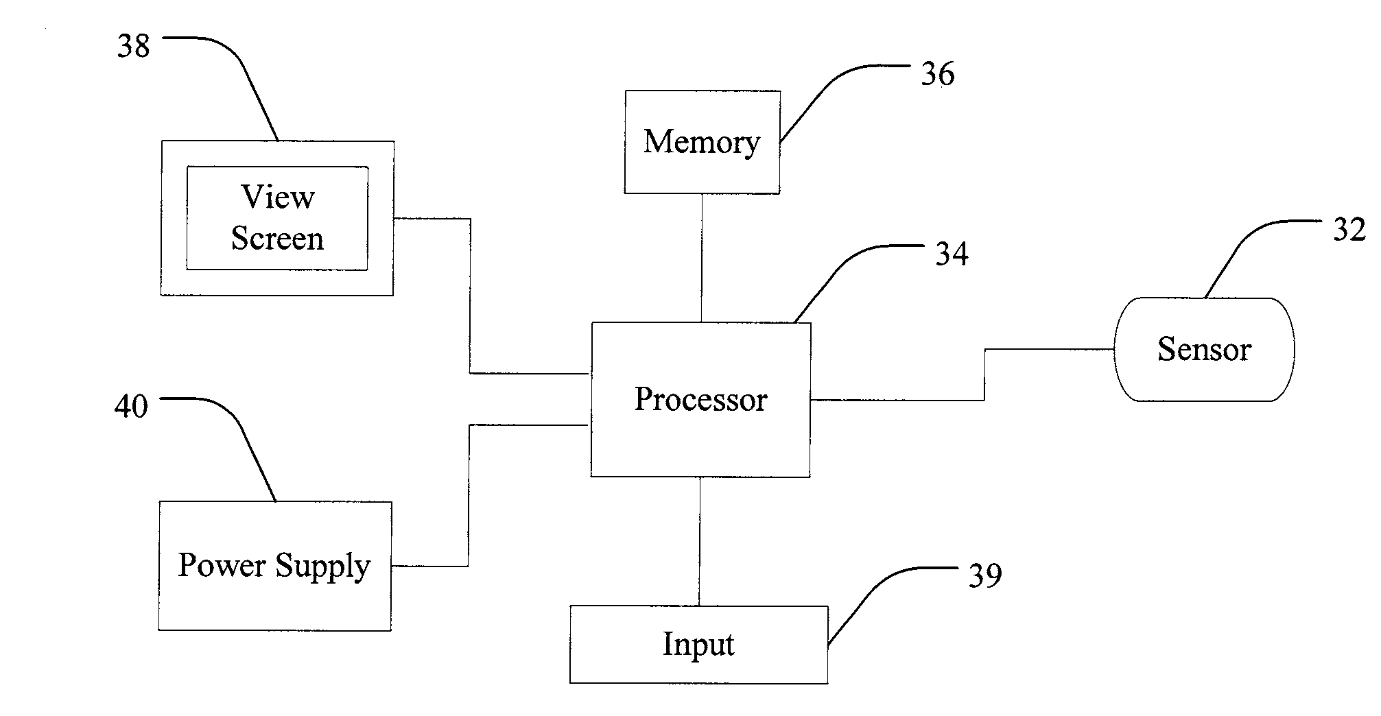
[0047]A 1.7 g Analog Devices ADXL203 MEMS two axis accelerometer is used in the following experiments. A 5 V power supply is used giving a nominal scale factor of 1000 mV / g. The value of the scale factor for this power supply typically varies by less than 2%. Given this level of accuracy in the scale factor calibration, the nominal value is assumed correct. 100 nF filtering capacitors are used to set the nominal bandwidth of the sensor output at 50 Hz and the nominal noise floor at 1.0 mg rms (1.0 mV rms), with a peak-to-peak noise estimate of 6 mg (6 mV).

[0048]A THK linear bearing rail and slider are used to constrain motion to one dimension and allow the data processing to focus solely on sensor-level noise rejection and bias estimation without the additional complications of higher dimensional navigation solutions. It is verified that the precise fit of the slider on the rail constrained their relative motion sufficiently that no measurable change...


PUM


Abstract

A method and system for tracking and updating bias in an inertial sensor by determining a maximum bias drift and a noise band for a sensor, determining a prior bias value of the sensor, and measuring a current bias value of the sensor. The method and system can further include calculating a bias difference between the prior bias value and the current bias value, and updating the prior bias value with the current bias value if the current bias value is within the noise band and the bias difference is less than or equal to the maximum bias drift.

Description

BACKGROUND[0001]1. Field of the Invention[0002]The present invention relates generally to tracking and updating bias in inertial sensor devices.[0003]2. Related Art[0004]Inertial measurement technology has been used since the 1920's in aviation with ballistics and space exploration applications following later in the twentieth century. Throughout this period, a solid knowledge base and sophisticated techniques for inertial measurement have been developed for applications where velocities and distances are measured using nautical miles or even astronomical units. Until recent years, applications better-suited to measurement using meters or millimeters generally did not utilize inertial measurement due to the prohibitive size, weight, and cost of the sensors. The introduction and steady improvement of sensors based on microelectromechanical systems (MEMS) and other small, less-expensive inertial sensors has opened the door to their use in such applications in the past decade.[0005]Str...

Claims


Application Information

Patent Timeline
Patent Type & Authority Applications(United States)
IPC IPC(8): G01R19/00
CPCG01C21/16G01R31/2829G01C21/188
Inventor MINOR, MARK A.JOHNSON, ERIC A.BAMBERG, STACY J. MORRIS
Owner UNIV OF UTAH RES FOUND
Learn More